Sludge treatment system

A sludge treatment and sludge technology, applied in sludge treatment, water/sludge/sewage treatment, dehydration/drying/concentrated sludge treatment, etc., can solve the problem of low drying efficiency, poor drying effect, complex structure, etc. problems, to achieve the effect of simple structure and improved space utilization

Active Publication Date: 2016-03-30
淮安中顺环保科技有限公司
View PDF6 Cites 0 Cited by
  • Summary
  • Abstract
  • Description
  • Claims
  • Application Information

AI Technical Summary

Problems solved by technology

[0006] Therefore, the technical problem to be solved by the present invention is to overcome the defects of low drying efficiency, poor drying effect and complex structure of the dr...

Method used


Image

  • Sludge treatment system
  • Sludge treatment system
  • Sludge treatment system

Examples


Embodiment 1

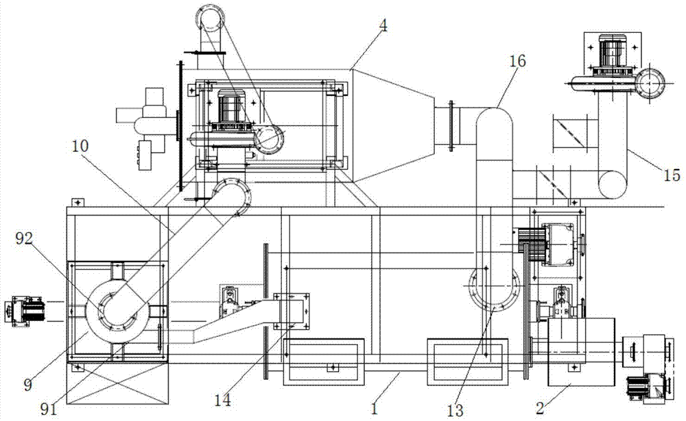
[0042] Such as Figure 5 As shown, this embodiment provides a sludge treatment system, including

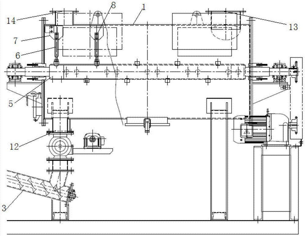
[0043] The transmission device has a two-stage transmission surface, the first-stage transmission surface 200 is located above the side of the second-stage transmission surface 300, the first-stage transmission surface 200 and the second-stage transmission surface 300 are connected by a transition device 500, and the transmission The device can transport the solid-liquid mixed sludge from the head end of the first-stage transmission surface 200 to the tail end of the first-stage transmission surface 200, and introduce it to the second-stage transmission surface 300 through the transition device, and transfer it from the second stage The head end of the surface 300 is transported to the tail end of the second stage transmission surface;

[0044] The dewatering structure includes a water outlet hole 400 arranged on each conveying surface, and a pressing plate 100 on each conveying...


PUM


Abstract

The invention relates to a sludge treatment system, comprising a conveying device, a dewatering structure and a drying device; the drying device comprises a furnace body, a charging device for charging materials into the furnace body, a collecting device for collecting dried materials in the furnace body, an air feeder introducing external air into the furnace body by a first air inlet and a stirring device for stirring and crushing the materials. The stirring device comprises a second rotary shaft which is arranged in a cavity of the furnace body in a penetrating manner, and the second rotary shaft has a venting cavity; the venting cavity is provided with a plurality of air jet holes; an air jet direction of the air jet holes is not coincided and is not parallel with a stirring direction of the stirring shaft and a stirring direction of a blade; when the materials are dried, hot air is introduced into the cavity of the furnace body by the first air inlet, and the second rotary shaft rotates to drive a stirring assembly on the second rotary shaft to continuously stir the materials along a radial direction and an axial direction of the second rotary shaft.

Description

technical field [0001] The invention relates to the technical field of sludge treatment, in particular to a sludge treatment system. Background technique [0002] Sludge is the product of the sewage treatment process, which contains a large amount of organic matter, heavy metals and molds, etc. If no follow-up treatment is added, it will cause serious pollution to the environment. Therefore, it is often necessary to concentrate and dehydrate the sludge, but after this treatment The moisture content of the final sludge is usually above 70%, and the sludge needs to be further dried. [0003] In the prior art, the drying system used for sludge drying is mostly structured as the drying system disclosed in the Chinese patent document CN201058838Y, including a furnace body, a feeder connected to the feed port of the furnace body, and an air outlet of the furnace body. Connected spray tower. Among them, the furnace body includes a transmission shaft arranged in the furnace body, ...

Claims


Application Information

Patent Timeline
IPC IPC(8): C02F11/12
CPCC02F11/12C02F11/121C02F11/122C02F11/16C02F2303/06
Inventor 王良源
Owner 淮安中顺环保科技有限公司
Why Eureka
Try Eureka