
Circularly polarized light separator design method based on artificial microstructure super surfaces

A technology of artificial microstructure and design method, applied in optics, instruments, optical components, etc., can solve problems such as lack of

Inactive Publication Date: 2016-06-01
ZHEJIANG UNIV
View PDF7 Cites 24 Cited by
  • Summary
  • Abstract
  • Description
  • Claims
  • Application Information

AI Technical Summary

Problems solved by technology

It is difficult to separate beams of different spin states in linearly polarized light in a homogeneous space due to the lack of effective tools

Method used


Image

  • Circularly polarized light separator design method based on artificial microstructure super surfaces
  • Circularly polarized light separator design method based on artificial microstructure super surfaces
  • Circularly polarized light separator design method based on artificial microstructure super surfaces

Examples


Embodiment 1

[0062] Symmetrical photon spin separation effect.

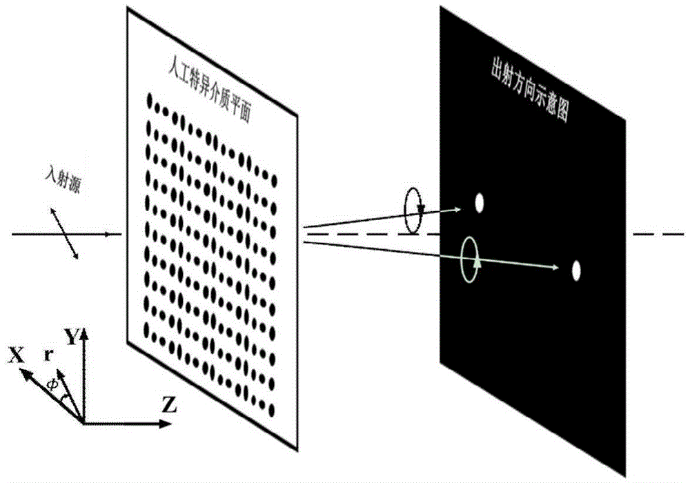
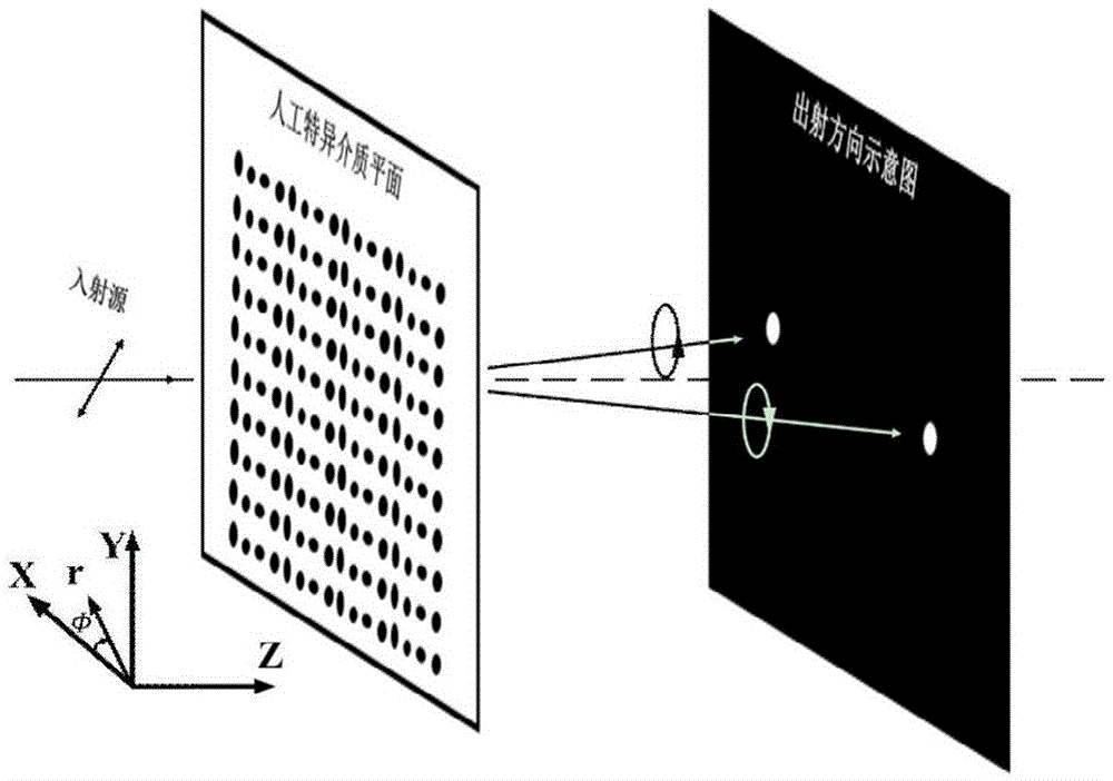
[0063] According to the above design method, an artificial microstructure metasurface is designed with a working wavelength of 1550nm to achieve a separation direction of 33.6° for the left-handed and right-handed components of the linearly polarized incident light. At the same time, by changing the polarization direction of the incident light, the The outgoing direction is reversed. And carry out relevant simulation verification.

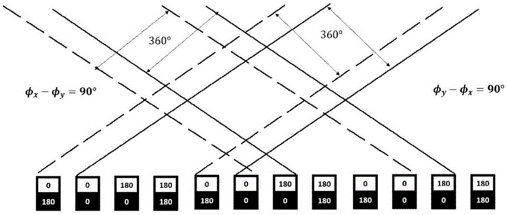
[0064] According to the emission direction of 33.6°, the structural unit is 700nm obtained by the formula (4). A phase gradient distribution of a 360° period is completed with 4 periodic structures to form a large periodic structure.

[0065] The phase gradients of the x and y polarizations are respectively designed to be 0°, 0°, 180°, and 180°. Similar to a grating structure, diffraction is produced in two directions simultaneously. At the same time, for the phase of the x, y polarization sta...


PUM


Abstract

The invention discloses a circularly polarized light separator design method based on artificial microstructure super surfaces. The circularly polarized light separator design method is characterized in that (1) a working wavelength can be selected in a range of from 600(mu)m to 20 (mu)m; and incident ray polarized light is irradiated on the artificial microstructure super surfaces vertically, and phase gradient distribution required by the artificial microstructure super surfaces can be calculated according to outgoing directions of left rotation and right rotation; by taking structural units of every four artificial microstructure super surfaces as a large periodic structure, the period of every structural unit can be calculated; (2) by taking column structures having low working wavelength losses as basic units of the artificial microstructure super surfaces, and concrete specific phase positions can be determined; (3) the corresponding specific realization structure can be designed according to the phase requirement of every basic unit. Under the condition of maintaining the high transmittance low loss, the left rotation component and the right rotation component of the ray polarized light can be symmetrically separated, and by changing the polarization direction of the incident light, the transmission directions of the outgoing left rotation and the outgoing right rotation can be exchanged.

Description

technical field [0001] The invention belongs to the field of optical information transmission and optical chip integration, and in particular relates to a design method of a circularly polarized light separator based on an artificial microstructure metasurface. Background technique [0002] With the development of information technology, high-definition television, mobile Internet, cloud computing and other technologies are profoundly changing people's lives, and the development of these technologies all put forward higher requirements for information transmission efficiency. Since Gao Kun invented optical fiber in 1965, human beings have greatly improved the information transmission rate, and on this basis, they have invented technologies such as wavelength division multiplexing to increase transmission capacity. In fact, the photon spin state is the intrinsic state of the photon, which is divided into left-handed and right-handed, and the two are orthogonal to each other. ...

Claims


Application Information

Patent Timeline
IPC IPC(8): G02B27/00G02B27/28
CPCG02B27/0012G02B27/28
Inventor 马云贵元军尹格
Owner ZHEJIANG UNIV
Learn More