
Sucker rod wellhead quick cleaning device and cleaning method thereof

A technology of cleaning device and sucker rod, applied in the field of oil well production, can solve the problems of high operating cost, low cleaning efficiency, large investment, etc., and achieve the effects of reducing thermal energy loss, good cleaning effect, and lowering cost of use

Inactive Publication Date: 2016-06-01
阜宁县宏达石化机械有限公司
View PDF7 Cites 5 Cited by
  • Summary
  • Abstract
  • Description
  • Claims
  • Application Information

AI Technical Summary

Problems solved by technology

The on-site cleaning device for sucker rods (oil pipes) developed by related companies is to achieve environmental protection by changing and increasing the current operating links. However, due to the large investment, high operating costs and poor efficiency of this set of devices, it has not been popularized and applied.
At present, most of the wellhead quick cleaning devices in use are relatively simple to clean and the cleaning efficiency is relatively low. Although a certain cleaning effect can be obtained, there is still a certain distance from the predetermined cleaning target. After the sucker rod (oil pipe) is taken out, it still needs to be cleaned. Further cleaning on the ground

Method used


Image

  • Sucker rod wellhead quick cleaning device and cleaning method thereof

Examples


Embodiment

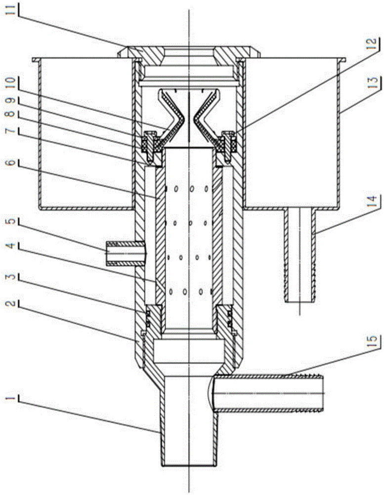
[0027] Example: A quick cleaning device for sucker rod wellhead, such as figure 1 As shown, it includes a lower joint 1, and a central pipe 6 and an outer pipe 2 respectively installed on the lower joint 1 through a threaded structure.

[0028] The lower end of the lower joint 1 is provided with an oil pipe buckle, and the oil pipe buckle is connected with the clamp head of the oil production wellhead, and the side of the lower joint 1 is provided with a dirty liquid outlet joint 15 .

[0029] The outer tube 2 is sleeved on the outside of the central tube 6, and the middle section of the inner wall of the outer tube 2 and the top of the central tube 6 are respectively provided with matching step surfaces, and the step surface on the inner wall of the outer tube 2 sits on the step surface at the top of the central tube 6 On the top, the gap between the outer tube 2 and the central tube 6 is isolated into a sealed cavity, the lower end of the outer tube 2 and the threaded conn...


PUM


Abstract

The invention discloses a sucker rod wellhead quick cleaning device, comprising a lower connector, and a central pipe and an outer pipe mounted on the lower connector. The outer pipe sleeves the central pipe, the side of the outer pipe is provided with a steam connector, the steam connector is communicated with a cavity between the central pipe and the outer pipe, forming a steam flow path, the wall of the central pipe is provided with at least two rows of a plurality of spouts inclined down from bottom to top, and the rows of spouts are peripherally and evenly distributed on the wall of the central pipe; a heat-proof curtain is further disposed between a port of the central pipe and a port of the outer pipe and sleeves the port of the central pipe. A sucker rod (tubing) is cleaned in time at a wellhead during trip-out, dirt brought from the bottom such as crude oil and paraffin deposit are cleaned into a dirt collection tank, oily water is avoided dropping the ground at the wellhead, and the environmental pollution problem caused during trip-out operation of the sucker rod (tubing) and ground thermal washing is effectively solved.

Description

technical field [0001] The invention belongs to the technical field of oil well production, and in particular relates to a matching tool used for reducing environmental pollution during oil field workover operations, especially a matching tool for timely and quickly cleaning the sucker rod at the wellhead when lifting the sucker rod for the pump inspection operation tool. Background technique [0002] At present, most oil fields in China are low-permeability oil layers, and most oil wells cannot be washed with clean water before operation. Therefore, some crude oil will be brought to the wellhead during the process of lifting the pump and hanging the string, causing the crude oil to fall to the ground, polluting the operation site and the environment . Oil pipes and sucker rods need to be stabbed and cleaned with steam on the ground to remove wax. Although plastic film and cofferdams are laid under the pipe rod bridge, and a shielding cloth is erected behind the oil pipe br...

Claims


Application Information

Patent Timeline
IPC IPC(8): E21B37/00
CPCE21B37/00
Inventor 顾静波刘海明
Owner 阜宁县宏达石化机械有限公司
Learn More