
Ion beam irradiation apparatus, and ion beam current homogenization method

A technology of irradiating device and beam current, which is applied to circuits, discharge tubes, electrical components, etc., to achieve high precision, avoid too large or too small, and improve accuracy

Active Publication Date: 2016-05-25
NISSIN ION EQUIP CO LTD
View PDF7 Cites 2 Cited by
  • Summary
  • Abstract
  • Description
  • Claims
  • Application Information

AI Technical Summary

Problems solved by technology

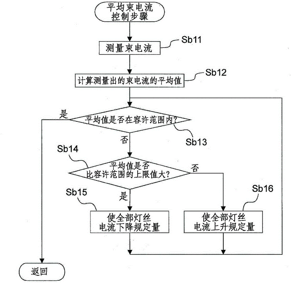
[0008] However, since any of the control devices described above controls the filament current based only on the average current of each group of beam current sensors, deviations occur in the measured currents of the beam current sensors in the group, that is, in the beam current at each position of the ion beam. , or in order to eliminate the above-mentioned deviation, it is necessary to repeatedly perform the uniformization step of the beam current
[0009] That is, since the ion beams emitted from each filament ideally have a Gaussian distribution, each beam current sensor originally has a different current value, so the beam current sensors are grouped and controlled based on only the above-mentioned average value. According to the method of Patent Document 1 or Patent Document 2, there is a limit in making the beam current uniform

Method used


Image

  • Ion beam irradiation apparatus, and ion beam current homogenization method
  • Ion beam irradiation apparatus, and ion beam current homogenization method
  • Ion beam irradiation apparatus, and ion beam current homogenization method

Examples


no. 1 approach

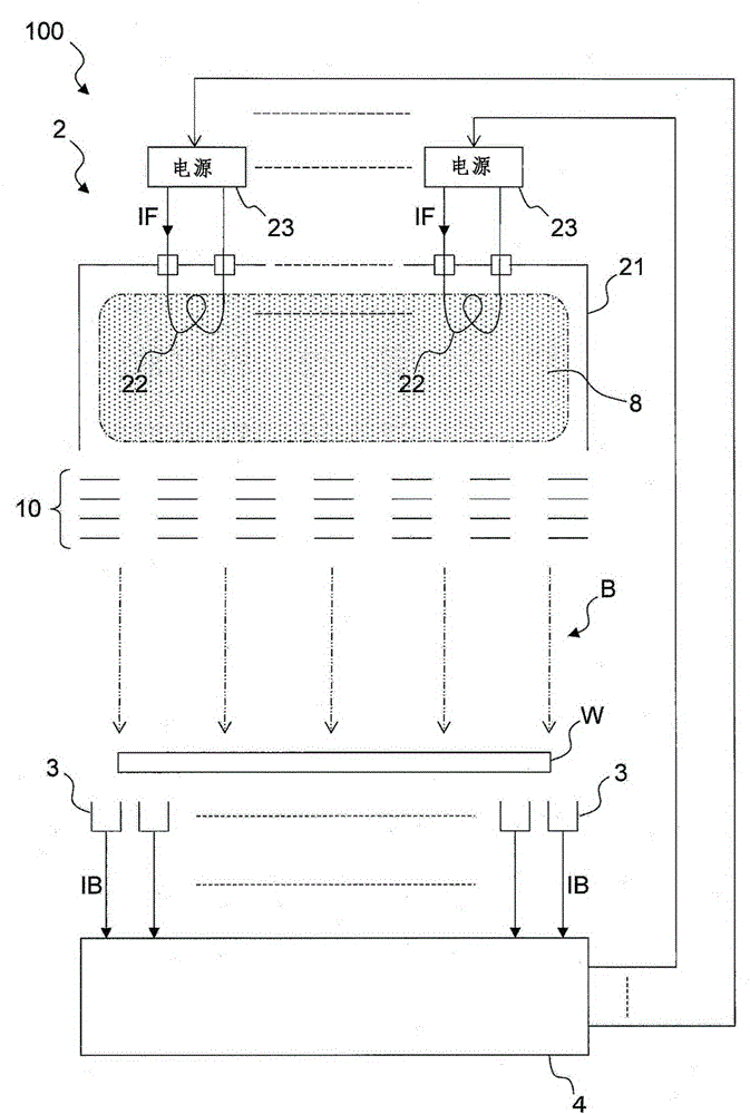
[0041] The ion beam irradiation apparatus 100 described above is used, for example, in a non-mass separation type ion implantation apparatus, such as figure 1 As shown, the large-area ion beam B extracted from the ion source 2 via the extraction electrode mechanism 10 directly irradiates the object W to be irradiated without passing through the mass separator to perform ion implantation. When ion implantation is performed, the object W to be irradiated can be mechanically scanned, for example, in the direction inwards and outwards on the paper, within the irradiation area of ​​the ion beam B as needed. The object to be irradiated W is, for example, a glass substrate, a semiconductor substrate, or the like.

[0042]The ion source 2 is also called a barrel ion source (or a multi-pole magnetic field type ion source), which includes: a plasma generating container 21 containing ion source gas; multiple (for example, 10) filaments 22 arranged on The plasma generating container 21 a...


PUM


Abstract

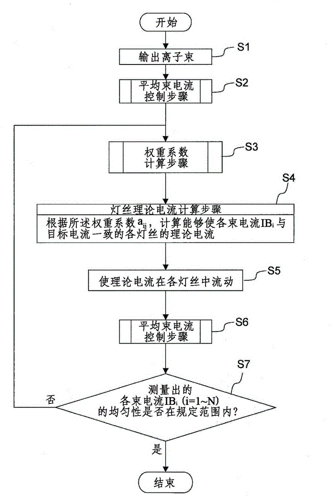
The invention provides an ion beam irradiation apparatus (100), being able to perform homogenization of beam current with good stability in a short time. In the uniform control step of homogenization of beam current, the control device performs the steps: a weighting coefficient calculation step: calculating the weighting coefficient that the influence degree of change of each filament current (IF) on each beam current (IB); and a filament theoretical current calculation step: calculating a theoretical current value, approaching the specific targetcurrent value, of each filament for each beam current (IB) according to the weighting coefficient obtained in the weighting coefficient calculation step.

Description

technical field [0001] The present invention relates to an ion beam irradiation device and the like for irradiating an ion beam to a wafer or the like. Background technique [0002] For example, in the manufacturing process of liquid crystal displays and semiconductor devices, ion beam irradiation equipment is used to inject impurity substances such as phosphorus (P) and boron (B) into processed objects such as liquid crystal glass substrates and semiconductor substrates. [0003] The ion source used in such an ion beam irradiation device includes a plasma generating container in which plasma is generated, and a plurality of filaments provided inside the plasma generating container, and is heated by passing an electric current through each of the filaments to release heat. The electrons collide with the material gas molecules in the plasma generation container to generate plasma, and the plasma is extracted by the extraction electrode system and accelerated into an ion beam....

Claims


Application Information

Patent Timeline
IPC IPC(8): H01J37/317
Inventor 平井裕也山元徹朗松本武
Owner NISSIN ION EQUIP CO LTD
Learn More