
Wavelength division multiplexing type non-contact online voltage monitoring system for power transmission line

A transmission line, wavelength division multiplexing technology, applied in the direction of measuring current/voltage, measuring device, measuring electrical variables, etc., can solve the problems that it is difficult to meet the lightning protection protection requirements of transmission lines, and the coupling weakening of parallel wires

Inactive Publication Date: 2016-05-25
CHONGQING UNIV
View PDF5 Cites 4 Cited by
  • Summary
  • Abstract
  • Description
  • Claims
  • Application Information

AI Technical Summary

Problems solved by technology

At present, most of the overvoltage monitoring systems for power transmission systems are installed inside the substation. When lightning waves are transmitted to the inside of the substation through long distances, they will be weakened by line loss, parallel wire coupling, lightning protection for various equipment, and complex refraction. and the complex electromagnetic environment in the substation, the lightning data recorded by the monitoring system is not the first-hand data, and it is difficult to meet the lightning protection protection requirements of transmission lines

Method used


Image

  • Wavelength division multiplexing type non-contact online voltage monitoring system for power transmission line
  • Wavelength division multiplexing type non-contact online voltage monitoring system for power transmission line
  • Wavelength division multiplexing type non-contact online voltage monitoring system for power transmission line

Examples


Embodiment Construction

[0024] In order to make the objectives, technical solutions, and advantages of the present invention clearer, the specific embodiments of the present invention will be described in further detail below.

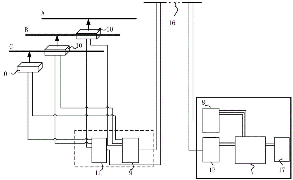
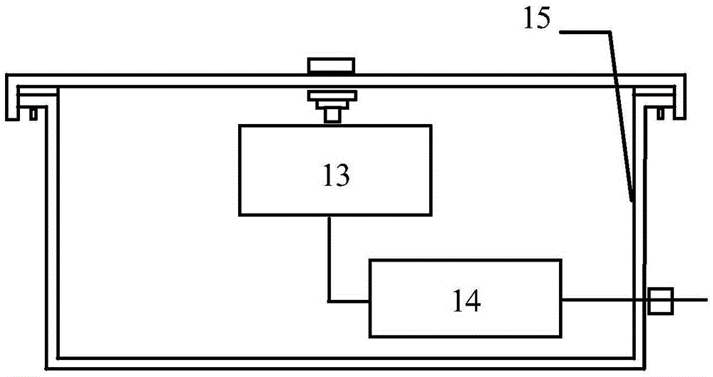
[0025] See Figure 1-4 , The wavelength division multiplexing type non-contact transmission line voltage online monitoring system of this embodiment includes

[0026] Multi-wavelength laser transceiver 7 for outputting and receiving laser;

[0027] The control-end wavelength division multiplexer 8 is used to couple lasers of different wavelengths output by the multi-wavelength laser transceiver device 7 into one optical fiber for transmission; in this embodiment, the output end of the control-end wavelength division multiplexer 8 passes through a pigtail The channel I of the optical fiber coupled overhead ground wire 16 is connected, and the channel I of the optical fiber coupled overhead ground wire 6 is connected to the input end of the monitoring end demultiplexer 9.

[0028] The...


PUM


Abstract

The invention aims at providing a wavelength division multiplexing type non-contact online voltage monitoring system for a power transmission line, and belongs to the technical field of power detection. The monitoring system comprises a multi-wavelength laser transmitting-receiving device, a control-end wavelength division multiplexer, a monitoring-end demultiplexer, at least one voltage sensor, a monitoring-end wavelength division multiplexer, a control-end demultiplexer and a data collector, wherein the multi-wavelength laser transmitting-receiving device is used to output and receive laser; the voltage sensor is arranged at a voltage monitoring point of the power transmission line; the control-end demultiplexer receives laser output by the monitoring-end wavelength division multiplexer, reduces the laser into multiple paths of laser of different wavelengths, and outputs the multiple paths of laser to the multi-wavelength laser transmitting-receiving device; and the data collector obtains voltage data of the monitoring end according to signals obtained by the multi-wavelength laser transmitting-receiving device. Each voltage sensor comprises a non-contact voltage induction unit and a photoelectric conversion unit, wherein the non-contact voltage induction units is used to sense the voltage of the power transmission line and loads the voltage on the photoelectric conversion unit, and the photoelectric conversion unit receives laser output by the monitoring-end wavelength division multiplexer.

Description

Technical field [0001] The invention belongs to the technical field of power detection, and specifically relates to a high-voltage transmission line voltage monitoring system. Background technique [0002] my country's electric power has entered a new stage of large generating units, large power grids, ultra-high voltage, informatization and automation. The stable and reliable operation of the power system is directly related to people's production and quality of life, as well as to the development and progress of social economy. Once an accident occurs in the power system, it will not only cause economic losses, but also affect the normal life of the people, endanger public safety, and cause serious social problems. Judging from the actual operating conditions of various countries, power system failures caused by lightning account for 40%-70% of the annual failures, and are the main hazard to the safe and stable operation of transmission lines. With the continuous improvement ...

Claims


Application Information

Patent Timeline
IPC IPC(8): G01R19/00
Inventor 杨庆韩睿司马文霞孙尚鹏袁涛刘通何彦宵
Owner CHONGQING UNIV
Learn More