
Control loop of working device of engineering operation equipment

A technology of working device and control circuit, which is applied in the field of hydraulic circuit, can solve problems such as difficulties in the layout of engineering operation equipment, and achieve the effects of improving operating efficiency, saving energy, and reducing temperature rise

Active Publication Date: 2016-05-25
TAIYUAN UNIV OF TECH
View PDF7 Cites 10 Cited by
  • Summary
  • Abstract
  • Description
  • Claims
  • Application Information

AI Technical Summary

Problems solved by technology

However, this method needs to add a third hydraulic cylinder on the basis of the original double hydraulic cylinder, which will change the structure of the original mechanical device, and it is difficult to apply it to the layout of engineering operation equipment.

Method used

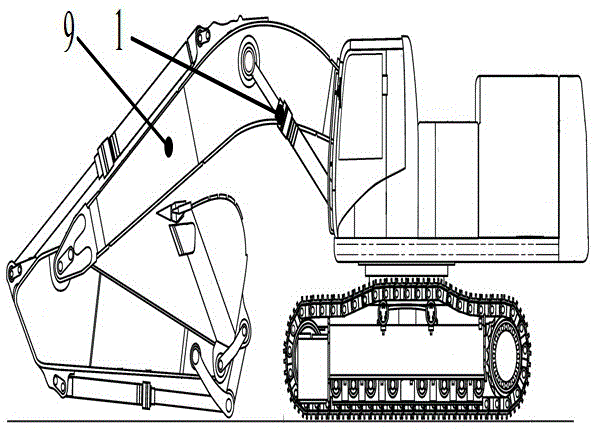
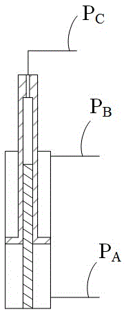

Image

  • Control loop of working device of engineering operation equipment
  • Control loop of working device of engineering operation equipment
  • Control loop of working device of engineering operation equipment

Examples


Embodiment 1

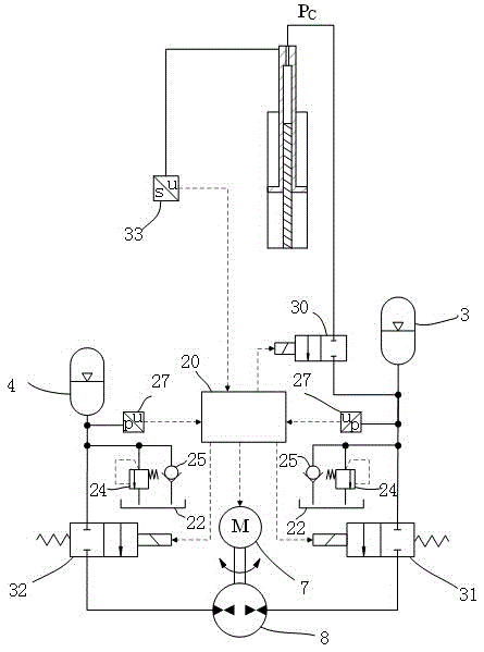
[0051] Such as Figure 7 As shown, in this embodiment, the working device 9 is driven by the boom hydraulic cylinder 1 to perform frequent up and down reciprocating movements. Boom hydraulic cylinder oil port P A It is connected to the high-pressure accumulator 3 via the first shut-off valve 30 . One working oil port of the hydraulic pump motor 8 is connected with the high-pressure accumulator through the second shut-off valve 31 , and the other working oil port is connected with the low-pressure accumulator 4 through the third shut-off valve 32 . The oil port of each accumulator is connected with a safety valve 24 and a check valve 25, wherein the high-pressure side of the safety valve is connected to the accumulator, the low-pressure side is connected to the oil tank 22, and the check valve is connected to the accumulator and the oil tank. The direction of fluid flow is from the tank to the accumulator. The hydraulic pump motor is driven by prime mover 7. Pressure sensor...

Embodiment 2

[0055] Such as Figure 8 As shown, in this embodiment, the liquid-pneumatic energy storage balance circuit is connected to the oil port P of the boom hydraulic cylinder 1 C ; The liquid-gas energy storage balance circuit includes a high-pressure accumulator 3, a safety valve 24 and a one-way valve 25, the high-pressure accumulator 3 is connected to the safety valve 24, and the safety valve 24 is connected to the oil tank 22, and the two oils of the safety valve 24 The port is connected with a one-way valve 25. The high-pressure accumulator is charged with high-pressure gas in advance to balance the working device and recover its potential energy. The drive circuit of the hydraulic cylinder adopts an open hydraulic circuit.

[0056] When the control signal is to lower the working device 9, the first controller coordinates and controls the four two-position two-way proportional valves 23 and the hydraulic pump 21 to drive the boom hydraulic cylinder to retract. When the press...


PUM


Abstract

The invention discloses a control loop of a working device of engineering operation equipment. The control loop is used for controlling a movable arm hydraulic cylinder of the engineering operation equipment and comprises a hydraulic engineering operation equipment working device body, the movable arm hydraulic cylinder, a hydraulic cylinder liquid-gas energy storage balance loop, a hydraulic cylinder driving loop and a control handle, wherein the movable arm hydraulic cylinder is connected with the hydraulic engineering operation equipment working device body and is a hydraulic cylinder with three accommodating cavities; the hydraulic cylinder liquid-gas energy storage balance loop is connected with a working oil opening of the movable arm hydraulic cylinder; the hydraulic cylinder driving loop is connected with the other two working oil openings of the movable arm hydraulic arm; the control handle is connected with the hydraulic cylinder driving loop. When the hydraulic engineering operation equipment working device body rises, flow for the hydraulic cylinder is reduced, so that the rising speed of the working device body can be accelerated to improve the working efficiency; when the working device body falls down, throttling heat at a hydraulic valve is reduced, temperature increase of a hydraulic system is reduced, the stability is improved, and the service life of a hydraulic element is prolonged.

Description

technical field [0001] The invention relates to a hydraulic circuit for controlling a working device of hydraulic engineering operation equipment, in particular to a control circuit for a boom lifting mechanism of hydraulic engineering operation equipment to reduce its working energy consumption. Background technique [0002] In engineering operation equipment, loaders and other mechanical devices driven by hydraulic cylinders that require frequent up and down reciprocating movements of the working device, usually due to the heavy weight of the working device itself, when the hydraulic cylinder drives it up, the hydraulic system needs to overcome its gravity to work. When the working device is lowered, the potential energy of the working device is converted into heat energy through the throttling of the hydraulic valve and consumed. This not only wastes energy, but also increases the oil temperature of the hydraulic system, increases the probability of system failure, and aff...

Claims


Application Information

Patent Timeline
Patent Type & Authority Applications(China)
IPC IPC(8): E02F9/22
CPCE02F9/22E02F9/2246E02F9/2264
Inventor 权龙夏连鹏郝惠敏黄家海葛磊
Owner TAIYUAN UNIV OF TECH
Learn More