
Crystalline silicon solar cell secondary printing front face electrode overprinting screen printing plate graph structure

A crystalline silicon solar cell and secondary printing technology, applied in the field of solar cells, can solve the problems of DP2 electrode and DP1 electrode dislocation, battery conversion efficiency drop, electrode aspect ratio drop, etc., to improve alignment accuracy and comprehensive performance , the effect of reducing usage

Inactive Publication Date: 2016-05-25
SHANGHAI ALEX NEW ENERGY
View PDF8 Cites 14 Cited by
  • Summary
  • Abstract
  • Description
  • Claims
  • Application Information

AI Technical Summary

Problems solved by technology

[0004] Secondary printing technology has become one of the effective methods to improve battery conversion efficiency, but the industrialized secondary printing technology still has the problem of misalignment and misalignment between the DP2 electrode and the DP1 electrode, which causes the electrode aspect ratio to decrease, The shading area increases and the short-circuit current decreases, which eventually leads to a decrease in battery conversion efficiency

Method used


Image

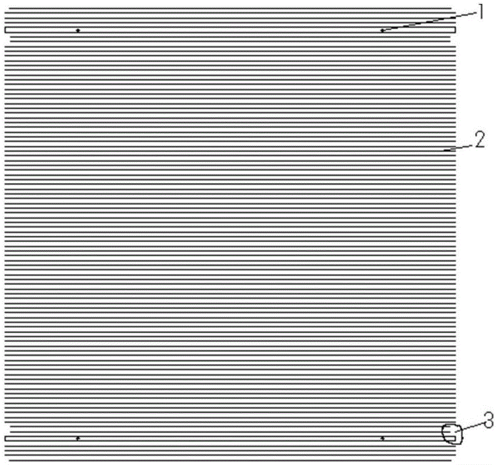
  • Crystalline silicon solar cell secondary printing front face electrode overprinting screen printing plate graph structure
  • Crystalline silicon solar cell secondary printing front face electrode overprinting screen printing plate graph structure
  • Crystalline silicon solar cell secondary printing front face electrode overprinting screen printing plate graph structure

Examples


Embodiment Construction

[0027] The technical solution of the present invention will be described in further detail below in conjunction with the accompanying drawings and specific examples. This embodiment is implemented on the premise of the technical solution of the present invention, and detailed implementation methods are provided, but the scope of protection of the present invention is not limited to the following the described embodiment.

[0028] figure 1 Shown is the DP1 graphic in the secondary printing overprint screen graphic, including Mark point 1, sub-grid line 2 and characteristic graphic 3, wherein the number of Mark point 1 is more than 3, and the number of sub-grid lines 2 is Several sub-grid lines 2 are parallel to each other, Mark point 1 is located between two sub-grid lines, and feature figure 3 is located at the top of the 5th, 6th, 7th, and 8th sub-grid lines from both ends of the graphic.

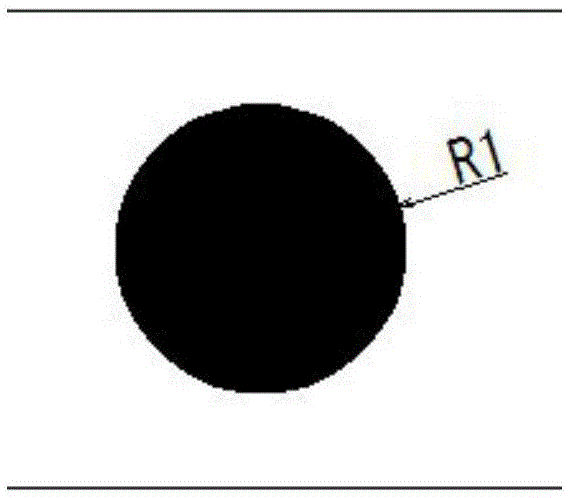
[0029] figure 2 It is an enlarged picture of Mark point 1 in the DP1 graphic. Mark ...


PUM


Abstract

The invention discloses a crystalline silicon solar cell secondary printing front face electrode overprinting screen printing plate graph structure which comprises a DP1 graph and a DP2 graph. The DP1 graph comprises an auxiliary grid line, a feature graph and a Mark point. The DP2 graph comprises a main grid line, an auxiliary grid line, a Mark point, a feature graph and a frame line. The DP1 graph and the DP2 graph are each provided with the Mark point and the feature graph so as to carry out observation judgment and adjustment optimization on the secondary printing alignment state, the probability that dislocation is caused to a DP1 electrode and a DP2 electrode is greatly lowered, the alignment precision of the secondary printing technology in a batch production is improved, the light shielding area is reduced, the short circuit current Isc of a cell is improved, and therefore the comprehensive performance of the solar cell is improved; only the DP2 graph is provided with the main grid line, and no grid line is designed in the DP1 graph, so that the using amount of positive silver paste is greatly reduced due to the design, and the production cost is reduced.

Description

technical field [0001] The invention relates to the field of solar cells, and more specifically relates to a novel solar cell secondary printing positive electrode screen pattern structure. Background technique [0002] Solar energy is clean, inexhaustible, and renewable energy, and silicon PN junction solar cells have developed into the dominant player in the photovoltaic market. The production of silicon PN junction solar cells uses silicon as the substrate, making suede on the surface, and then diffusing to make a PN junction, then etching the edge, then using PECVD to coat a passivation anti-reflection film, and finally making it through screen printing and sintering technology electrode. [0003] Traditional screen printing prepares the front electrode by single printing, the electrode morphology is limited, and it is difficult to obtain the ideal aspect ratio. The second printing technology prepares the front electrodes by printing DP1 and DP2 twice. The electrodes p...

Claims


Application Information

Patent Timeline
Patent Type & Authority Applications(China)
IPC IPC(8): B41F15/36H01L31/0224
CPCB41F15/36H01L31/022425Y02E10/50
Inventor 麻晓明卢庆国
Owner SHANGHAI ALEX NEW ENERGY
Learn More