
Machining Method of Turbine Blade Sawtooth Shroud Structure

A technology of turbine blades and processing methods, which is applied in metal processing equipment, manufacturing tools, grinding machines, etc., can solve the problems of complex processing procedures and unsmooth processing surfaces of zigzag blade crowns, achieve convenient processing, eliminate tool marks, and ensure surface effect

Active Publication Date: 2017-12-19
CHINA AVIATION POWER MACHINE INST
View PDF8 Cites 0 Cited by
  • Summary
  • Abstract
  • Description
  • Claims
  • Application Information

AI Technical Summary

Problems solved by technology

[0004] The present invention provides a method for processing the zigzag blade crown structure of the turbine blade to solve the existing method for processing the zigzag blade crown of the power turbine blade. Two sets of grinding wheels are required to process the zigzag blade crown, and the processing procedure is relatively complicated; The two sets of grinding wheels must have "joint tool marks" at the transition point, resulting in a technical problem that the processed surface of the zigzag blade crown is not smooth

Method used


Image

  • Machining Method of Turbine Blade Sawtooth Shroud Structure
  • Machining Method of Turbine Blade Sawtooth Shroud Structure
  • Machining Method of Turbine Blade Sawtooth Shroud Structure

Examples


Embodiment Construction

[0030] The embodiments of the present invention will be described in detail below with reference to the accompanying drawings, but the present invention can be implemented in various ways defined and covered below.

[0031] image 3 It is a block flow diagram of the processing method of the sawtooth blade shroud structure of the turbine blade according to the preferred embodiment of the present invention; Figure 4 It is one of the structural schematic diagrams of the processing state of the first working face in the preferred embodiment of the present invention; Figure 5 It is the second structural schematic diagram of the processing state of the first working face in the preferred embodiment of the present invention; Figure 6 It is one of the structural schematic diagrams of the processing state of the second working face in the preferred embodiment of the present invention; Figure 7 It is the second structural schematic diagram of the processing state of the second wor...


PUM


Abstract

The invention discloses a method for machining a sawtooth-shaped blade crown structure of a turbine blade. The method comprises the following steps that a, a stereoscopic coordinate system is established according to the relative positions of the non-work face of a blade crown and a grinding wheel; b, the posture of the blade is adjusted according to the stereoscopic coordinate system and the first work face of the designed first side face of the blade crown, the first work face is made to correspond to the grinding wheel, and the first work face and the first non-work face on the same side are machined through the grinding wheel; c, after the first work face and the first non-work face are machined, the blade is turned over, deflection of the blade is carried out, the second work face of the designed second side of the blade crown is made to correspond to the grinding wheel, and the second work face is machined through the grinding wheel; d, the grinding wheel moves and deviates in the radial direction of the grinding wheel, and the second non-work face on the same side with the second work face is machined; e, the sawtooth-shaped blade crown structure is machined through the same grinding wheel. Machining is convenient and fast. Machining cost can be reduced. It can be guaranteed that the surfaces of the faces to be machined are smooth.

Description

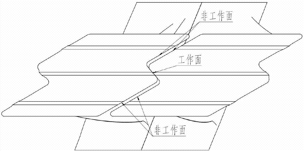
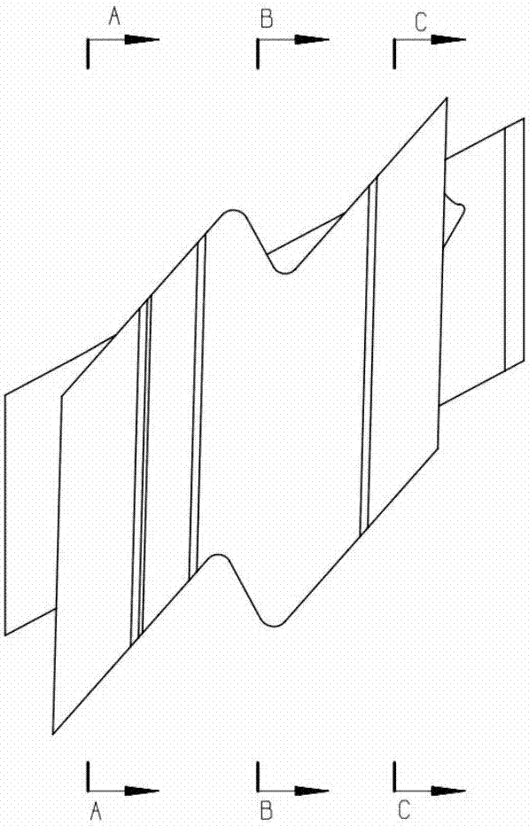
technical field [0001] The invention relates to the technical field of machining turbine blades of aero-engines, in particular to a machining method for a serrated shroud structure of a turbine blade. Background technique [0002] The sawtooth crown of the turbine blade of an aeroengine is as figure 1 As shown, it consists of 2 working faces and 4 non-working faces. The working surfaces of adjacent two groups of blades are closely attached to each other, and a certain gap must be ensured on the non-working surfaces. Traditional Ye Guanru figure 2 as shown in Figure 2a The "A-A profile" and such as Figure 2c The "C-C section" is all sectioned on the non-working plane. It can be seen that the non-working plane and the center (X-Y plane) do not form an angle, such as Figure 2b The working surface "B-B section and the center (X-Y plane) form a certain angle. During processing, it is necessary to grind the two non-working surfaces first, and then grind the working surfac...

Claims


Application Information

Patent Timeline
Patent Type & Authority Patents(China)
IPC IPC(8): B24B19/14B24B1/00
CPCB24B1/00B24B19/14
Inventor 宋石平李鑫陶冶科余索远王芳
Owner CHINA AVIATION POWER MACHINE INST
Learn More