Liquid crystal display device

A technology of liquid crystal display device and liquid crystal layer, which can be applied in the fields of instruments, nonlinear optics, optics, etc., and can solve problems such as difficulty in using "view angle compensation plate integrated polarizing plate, unfavorable cost, etc.

Active Publication Date: 2020-11-13
STANLEY ELECTRIC CO LTD
View PDF7 Cites 0 Cited by
  • Summary
  • Abstract
  • Description
  • Claims
  • Application Information

AI Technical Summary

Problems solved by technology

However, in the case of employing a structure based on a known technology, it is difficult to use the above-mentioned "viewing angle compensating plate integrated polarizing plate", which is disadvantageous in terms of cost.

Method used


Image

  • Liquid crystal display device
  • Liquid crystal display device
  • Liquid crystal display device

Examples


Embodiment 1

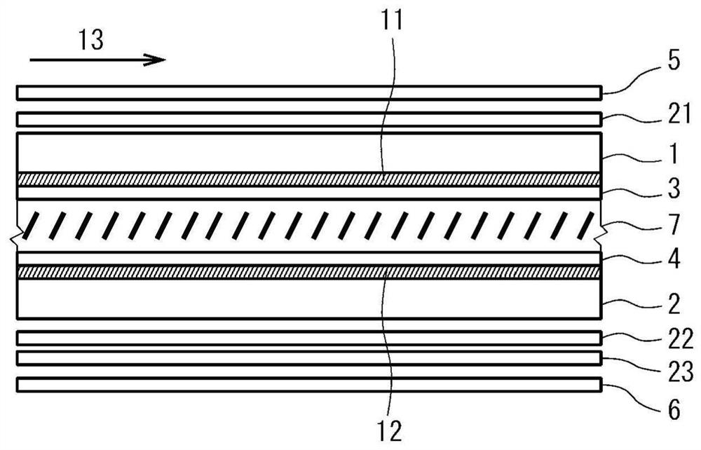
[0057] ·Is the above figure 1 , 2 In the structure shown in , a TAC film as a protective film of the polarizing plate is disposed between the polarizing layer of the polarizing plate and the optical plate

[0058] ·Liquid crystal layer thickness: 4μm

[0059] ·Liquid crystal material: △n=0.0914, △ε=-5.1, no chiral material added

[0060] ・Pretilt angle: 89.5 degrees (the first substrate and the second substrate both have this pretilt angle)

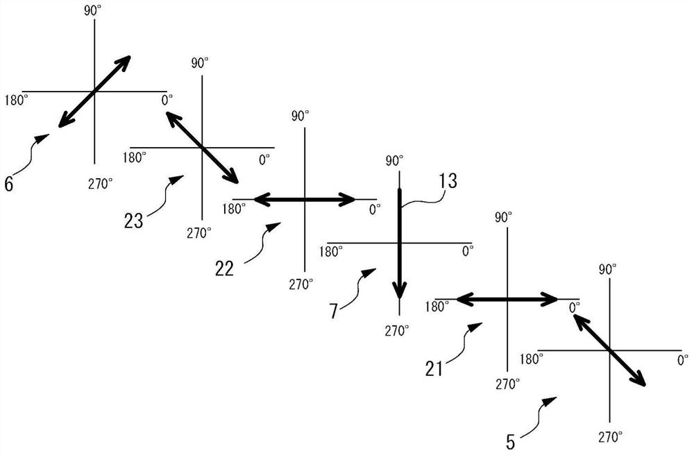
[0061] ・Alignment direction at the center of the layer thickness direction of the liquid crystal layer when a voltage is applied: 6 o'clock direction (270° direction)

[0062] 1 / 4 wavelength plate: a retardation plate with an in-plane retardation of 140nm and positive uniaxial optical anisotropy (positive A plate)

[0063] ・Optical plate: Negative biaxial film with in-plane retardation of 55nm and thickness direction retardation of 220nm

[0064] Light source: standard light source D65

[0065] ・Emulator: Liquid crystal display emul...

Embodiment 2

[0067] ·Is the above figure 1 , 2 In the structure shown in , no TAC film, etc. as a protective film of the polarizing plate is placed between the polarizing layer of the polarizing plate and the optical plate

[0068] ·Other conditions are identical with embodiment 1

Embodiment 3

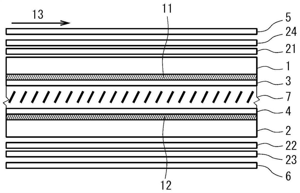
[0070] ·Is the above image 3 , 4 In the structure shown in , no TAC film, etc. as a protective film of the polarizing plate is placed between the polarizing layer of the polarizing plate and the optical plate

[0071] ・Optical plate: Negative biaxial film with in-plane retardation of 55nm and thickness direction retardation of 124nm

[0072] ·Other conditions are identical with embodiment 1


PUM

PropertyMeasurementUnit
angleaaaaaaaaaa

Abstract

PROBLEM TO BE SOLVED: To provide a vertical alignment type liquid crystal display device with a normally white mode, which inexpensively suppresses a color shift occurring when the device is observed in lateral directions.SOLUTION: The liquid crystal display device includes a first substrate 1, a second substrate 2, a liquid crystal layer 7, a first polarizing plate 5, a second polarizing plate 6, and first to third optical plates 21, 22, 23. Absorption axes of the polarizing plates are disposed substantially orthogonal to each other and at an angle of about 45 with respect to an alignment direction of the liquid crystal layer at substantially the center in a layer thickness direction when an electric field is applied. The first optical plate 21 is a quarter-wave plate having an in-plane slow axis disposed at an angle of about 45° with respect to the absorption axis of the first polarizing plate 5. The second optical plate 22 is a quarter wave plate having an in-plane slow axis disposed at an angle of about 45° with respect to the absorption axis of the second polarizing plate 6. The third optical plate 23 has negative biaxial optical anisotropy and has an in-plane slow axis disposed substantially orthogonal to the absorption axis of the first polarizing plate 5.SELECTED DRAWING: Figure 1

Description

technical field [0001] The present invention relates to a vertical alignment type liquid crystal display device. Background technique [0002] The basic configuration of a vertical alignment liquid crystal display device includes two substrates facing each other, a vertical alignment liquid crystal layer provided between these substrates, and two polarizing plates respectively arranged outside the substrates. In this vertical alignment type liquid crystal display device, the absorption axes of the two polarizing plates are arranged to be perpendicular to each other (crossed Nicol arrangement), and a viewing angle compensating plate is arranged between the substrate and the polarizing plates, thereby, Very good dark display can be obtained when viewed from the front and when viewed from an oblique direction, and excellent normally black display can be realized. [0003] In such a vertical alignment type liquid crystal display device, by further providing a reflection plate o...

Claims


Application Information

Patent Timeline
Patent Type & Authority Patents(China)
IPC IPC(8): G02F1/13363G02F1/1335
CPCG02F1/133528G02F1/13363G02F1/133638
Inventor 岩本宜久
Owner STANLEY ELECTRIC CO LTD
Why Eureka
Try Eureka