
Pulverized coal fluidizing and injection device for blast furnace

A blowing device, pulverized coal technology, applied in blast furnaces, blast furnace details, furnaces, etc., can solve problems affecting pulverized coal transportation, uneven air distribution, etc., to improve the fluidization effect, ensure uniformity and stability, and improve The effect of stability

Inactive Publication Date: 2016-05-18
SHANDONG IRON & STEEL CO LTD
View PDF6 Cites 3 Cited by
  • Summary
  • Abstract
  • Description
  • Claims
  • Application Information

AI Technical Summary

Problems solved by technology

[0003] At present, the fluidizing gas inlet pipe is generally directly inserted into the fluidizing chamber below the fluidizing plate. This structure makes the distribution of the fluidizing gas uneven in the fluidizing chamber, especially in the most important central area of ​​the fluidizing chamber. problem, thus affecting the transportation of pulverized coal

Method used


Image

  • Pulverized coal fluidizing and injection device for blast furnace
  • Pulverized coal fluidizing and injection device for blast furnace
  • Pulverized coal fluidizing and injection device for blast furnace

Examples


Embodiment 1

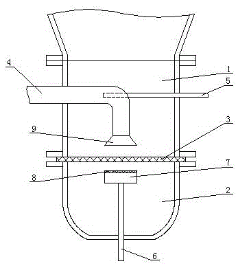
[0027] Such as figure 1 As shown, the present invention includes an injection chamber 1 and a fluidization chamber 2 , the fluidization chamber 2 is arranged below the injection chamber 1 , and the fluidization chamber 2 communicates with the injection chamber 1 through a fluidization plate 3 . The pulverized coal conveying pipe 4 enters the spray chamber 1 from one side of the spray chamber 1 and then bends vertically downward, and the inlet end 9 of the pulverized coal conveying pipe is trumpet-shaped. The pulverized coal air supply pipe 5 enters the pulverized coal conveying pipe 4 after entering the pulverized coal injection chamber 1 from the other side of the pulverized coal injection chamber. The fluidization gas inlet pipe 6 extends into the fluidization chamber 2 , and the outlet end of the fluidization gas inlet pipe 6 is provided with a fluidization gas distribution device, which is located in the central area of ​​the fluidization chamber 2 . One end of the fluidi...

Embodiment 2

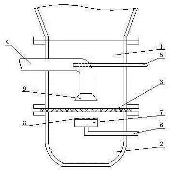
[0035] Such as figure 2 As shown, the difference between this embodiment and Embodiment 1 is that one end of the fluidizing gas inlet pipe 6 communicates with the bottom of the fluidizing gas distribution device, and the other end of the fluidizing gas inlet pipe 6 is bent from the fluidization chamber 2 side protrudes. This structural design is beneficial to save the space in the lower part of the fluidization chamber, and avoids the unfavorable construction and maintenance caused by not reserving the lower space during installation.

Embodiment 3

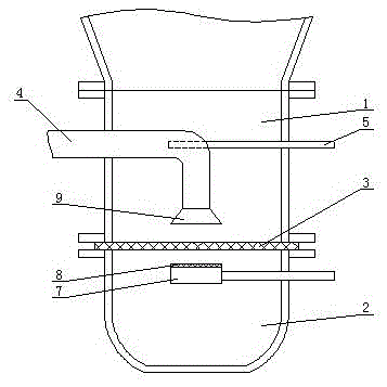
[0037] Such as image 3 As shown, the difference between this embodiment and Embodiment 1 is that one end of the fluidizing gas inlet pipe 6 communicates with one side of the fluidizing gas distribution device, and the other end of the fluidizing gas inlet pipe 6 connects with one side of the fluidizing chamber 2 side out. This structural design is beneficial to save the space in the lower part of the fluidization chamber, and avoids the unfavorable construction and maintenance caused by not reserving the lower space during installation.


PUM


Abstract

The invention relates to a pulverized coal fluidizing and injection device for a blast furnace. The pulverized coal fluidizing and injection device for the blast furnace comprises an injection chamber and a fluidizing chamber; the fluidizing chamber is arranged below the injection chamber; the fluidizing chamber communicates with the injection chamber through a fluidizing plate; after entering the injection chamber from one side of the injection chamber, a pulverized coal conveying pipe vertically bends downward; after entering the injection chamber from the other side of the injection chamber, a pulverized coal blowdown pipe extends into the pulverized coal conveying pipe; a fluidizing gas inlet pipe extends into the fluidizing chamber; the outlet end of the fluidizing gas inlet pipe is provided with a fluidizing gas distribution device; and the fluidizing gas distribution device is located in a central region of the fluidizing chamber. The pulverized coal fluidizing and injection device disclosed by the invention is reasonable in structural design, and fluidizing gas is enabled to be evenly distributed in the fluidizing chamber, especially the most important central region of the fluidizing chamber, so that uniformity and stability of pulverized coal conveyance are ensured, a stability degree of a furnace condition of the blast furnace is increased, and energy saving and emission reduction of the blast furnace are promoted.

Description

technical field [0001] The invention relates to a pulverized coal fluidized injection device for a blast furnace. Background technique [0002] The blast furnace used for ironmaking needs to inject pulverized coal into the blast furnace in order to reduce coke consumption, reduce production cost and improve production efficiency. In pulverized coal injection, the pulverized coal fluidization method is used to make the pulverized coal in a fluidized state, increase the fluidity of the pulverized coal, and reduce the pulsation injection. It is the main technology to improve the pulverized coal transportation capacity and the injection effect measure. The pulverized coal fluidized injection device is installed at the lower part of the pulverized coal tank. When pulverized coal is injected into the blast furnace, the pulverized coal in the pulverized coal tank must first form a suspended fluidized state, and then it can be injected into the blast furnace through the pipeline. ...

Claims


Application Information

Patent Timeline
IPC IPC(8): C21B5/00
CPCC21B5/003
Inventor 辛虹霓吴春顺袁宪强高新运刘德楼马桂娥陈丽孙艳红周文林
Owner SHANDONG IRON & STEEL CO LTD
Learn More