
Pneumatic punching mechanism

A kind of pneumatic punching and cylinder technology, which is used in perforating tools, metal processing equipment, manufacturing tools, etc., can solve the problems of easy out-of-tolerance, inability to achieve batch production, uneven hole quality, etc. The effect of tolerance

Inactive Publication Date: 2016-05-18
CHANGHE AIRCRAFT INDUSTRIES CORPORATION
View PDF6 Cites 0 Cited by
  • Summary
  • Abstract
  • Description
  • Claims
  • Application Information

AI Technical Summary

Problems solved by technology

This method cannot achieve batch production and the quality of the processed holes is not uniform, and it is easy to appear out of tolerance;
[0005] 3. To remake the mold, this method has a long cycle, large investment and uneconomical

Method used


Image

  • Pneumatic punching mechanism
  • Pneumatic punching mechanism

Examples


Embodiment Construction

[0017] The present invention will be described in further detail below, and its working principle will be set forth.

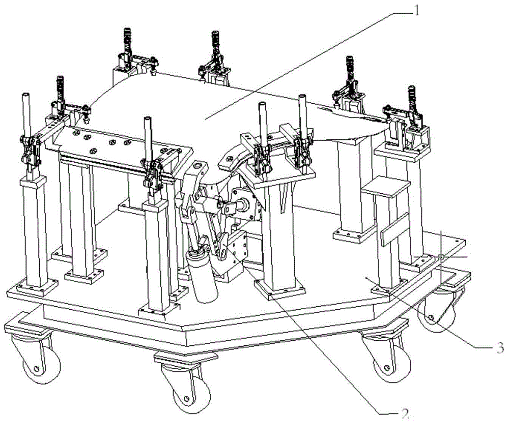
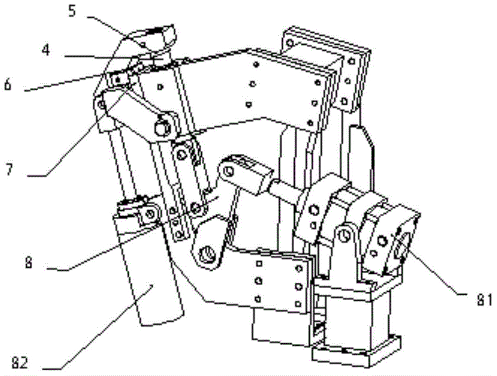
[0018] figure 2 The punching mechanism shown is a detailed diagram of the present invention, which is combined with other functional components to form a figure 1 Drilling jig shown; place the sheet metal parts to be reprocessed on the pneumatic punching mechanism of the drilling jig, use positioning pins and pressing devices to accurately position the sheet metal parts, clamp them firmly and manually press them with a compactor sheet metal parts;

[0019] Ventilate the CK1B63 cylinder 82, the cylinder starts to work, and drives the die 5 to move. When the limit block 6 and the limit block 7 are completely fitted, the die 5 is positioned accurately, the driving force of the cylinder is converted into a pressing force, and the die 5 is pressed. Tighten the profile of the part and play the role of the blank holder;

[0020] When the die 5 is accurately posit...


PUM


Abstract

The invention belongs to punching techniques for sheet metal parts, and particularly relates to a pneumatic punching device. By the adoption of the punching device, when the design of a medium or large batch of produced sheet metal parts is changed and functional holes, such as wire holes, are added, batch production can be conducted reliably on the premise that the number of molds is not increased. A pneumatic way is adopted by the punching device, and target holes are punched by means of the propelling force of air cylinders. According to the punching device, a punching female die and a blank holder are combined into a whole, the CK1B63 air cylinder (82) is used for driving the female die and pressing the parts, and after the parts are pressed, the MBT80 air cylinder (81) works to drive a male die through a pressing plate (8) to punch the target holes. The mechanism is high in positioning precision, proper in punching force and particularly suitable for punching supplementary holes (with the hole diameter phi being smaller than 20 mm) of a batch of sheet metal parts.

Description

technical field [0001] The invention belongs to the field of mechanical design and tooling manufacturing. Background technique [0002] In the design of aircraft or automobile sheet metal parts, due to the change of aircraft or automobile sheet metal parts, the manufacturing basis of tooling has changed. In many cases, some process holes are added to the sheet metal parts, such as: wire threading holes, water leakage Holes, openings, etc. When this happens, the following methods are usually used to supplement the sheet metal parts: [0003] 1. Rework the mold and increase the punching mechanism; due to the constraints of the overall structure of the mold, it is often impossible to increase in many cases; [0004] 2. Carry out supplementary processing on the sheet metal parts manually, and manually repair and grind out additional holes. This method cannot achieve batch production and the quality of the processed holes is not uniform, and it is easy to appear out of toleran...

Claims


Application Information

Patent Timeline
Patent Type & Authority Applications(China)
IPC IPC(8): B21D28/34B21D43/00
Inventor 龙勇华熊明高王亚贝炜
Owner CHANGHE AIRCRAFT INDUSTRIES CORPORATION
Learn More