Assembly with friction arrangement

A technology of friction devices and components, applied in the direction of friction clutches, non-mechanical drive clutches, electric clutches, etc., can solve the problems of holding torque, not being able to hold positions, holding currents, etc., and achieve the effect of optimizing efficiency

Active Publication Date: 2016-05-11
SCHAEFFLER TECH AG & CO KG
View PDF10 Cites 5 Cited by
  • Summary
  • Abstract
  • Description
  • Claims
  • Application Information

AI Technical Summary

Problems solved by technology

[0007] For example, especially in actuators, such as hydrostatic clutch actuators (Hydrostatic Clutch Actuator—abbreviated HCA), in efficiency-optimized screw drives (such as PWG) driven by means of electric motors, there is the following problem: In the case of an electric motor, a holding current and thus a holding torque is required, since the screw drive (eg in a PWG) is not self-locking, wherein the hydrostatic clutch actuator operates relative to the load, eg the clutch characteristic curve
[0008] A significant disadvantage of such actuators is that they require a permanent holding current or are not able to hold the position in the event of a current interruption / fault (e.g. cable short circuit, plug dropout)
In the case of clutches that are opened by the actuator, there is then a high risk of undesired closing of the clutch

Method used


Image

  • Assembly with friction arrangement
  • Assembly with friction arrangement
  • Assembly with friction arrangement

Examples


Embodiment Construction

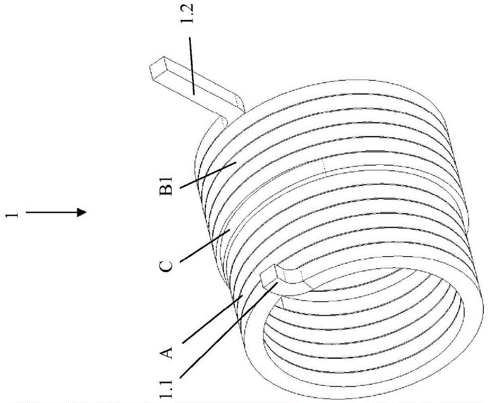
[0067] according to figure 1 and 2 , the first area A serving as a wrap spring (Eitelwan formula) has a first end 1.1 which is bent radially outwards, wherein a constant friction is established on the end 1.1 or via the first A constant or variable pre-interference of area A to the hub (outer diameter) to create friction. Furthermore, there is a second region B1 serving as a torsion spring with a second end 1 . 2 , which is likewise bent radially outward. Transition region C connects regions A and B to each other. The inner and outer diameters of the helix are larger in regions B1 and C than in region A.

[0068] The same width b and height H of the cross-section of the helix are present in all regions.

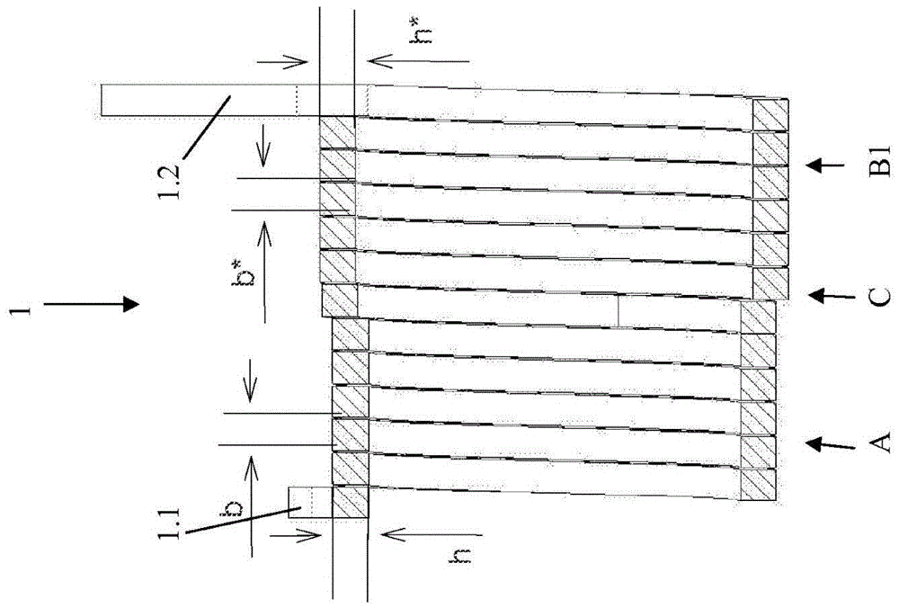
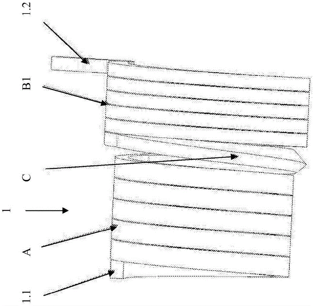
[0069] according to image 3 (three-dimensional view) and 4 (longitudinal section), the torsion spring 1 likewise has regions A, B1, C, wherein region C is however twisted by 90°. The rectangular cross-section of the helix thus has a height h and a width b in the first...


PUM


Abstract

The invention relates to an assembly with a friction arrangement having at least two components that can rotate relative to each other, more particularly for operating a clutch of a motor vehicle, wherein between the components that can rotate relative to each other there is provided a coil spring which influences the efficiency / friction when a relative movement of the components takes place, and the assembly is integrated together with a friction arrangement in a gearbox and / or an actuator.

Description

technical field [0001] The invention relates to an assembly with a friction device having at least two components that are rotatable relative to one another, especially for use in transmissions and / or actuators. Background technique [0002] Actuators are used, for example, to operate a clutch of a vehicle and are capable of converting rotational movement of one component into axial movement of another. [0003] From the reference document DE 10 2012 209 883 A1 is known a lever system for actuating a torque transmission device, such as a clutch in a drive train of a motor vehicle, which has a lever which is rotatably mounted on a bearing point about a hinge and The lever has a force introduction point that is displaceable parallel to the rotational axis of the torque transmission device and is operatively connected to the actuation actuator. In this case, the actuator itself can be any type of linear actuator, for example a PWG actuator (PWG=planetary roller screw gear), a ...

Claims


Application Information

Patent Timeline
Patent Type & Authority Applications(China)
IPC IPC(8): F16D13/08F16D13/50F16D28/00
CPCF16D13/08F16D13/50F16D28/00F16D29/005F16D2023/123
Inventor 拉尔斯·舒曼拉兹洛·曼彼得·格雷布
Owner SCHAEFFLER TECH AG & CO KG
Why Eureka
Try Eureka