
Suspension and body attachment system and differential pressure suit for body weight support devices

A support device, clothing technology, applied in the field of portable systems, which can solve the problems of poor pre-walking and balance training, limited range of motion, etc.

Active Publication Date: 2016-05-11
LITE RUN
View PDF24 Cites 12 Cited by
  • Summary
  • Abstract
  • Description
  • Claims
  • Application Information

AI Technical Summary

Problems solved by technology

When supported by the straps during BWS training, any mediolateral movement is limited by the medial-guided reaction force component, which will help stabilize the body in the frontal position, reducing or even eliminating the need for APA, thereby enabling pre-gait less effective with balance training
Additionally, the shoulder straps and linkages create localized pressure points and stresses on the body and limit the range of motion of the body and its extremities

Method used


Image

  • Suspension and body attachment system and differential pressure suit for body weight support devices
  • Suspension and body attachment system and differential pressure suit for body weight support devices
  • Suspension and body attachment system and differential pressure suit for body weight support devices

Examples


example 1

[0247] Example 1: Mobile support device

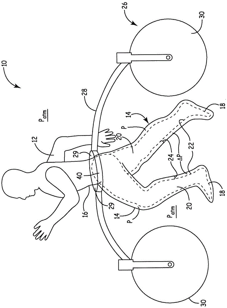
[0248] Rigid straps consisted of bent rigid aluminum strips 1 inch wide and 1 / 8 inch thick. The strips are elliptical. The pulleys are attached to the belt as described below. Two pulleys are attached at the midpoint of the front and back of the belt, and the two pulleys are Figure 47 The sides in the structure shown are joined at midpoints. Two additional pulleys are now shown attached to the left and right of each belt. One of the pulleys connects on each side from the pulley at the midpoint forward, and the other pulley connects on each side from the pulley at the midpoint toward the rear. To attach the pulleys to the trousers, the rigid support bar (2014) consists of a 1 / 8" thick 3 / 4" wide strip of aluminum that is inserted into a sleeve sewn into the trousers, as Figure 46 shown. Rope springs made of low-stretch material are passed alternately over belt pulleys and garment pulleys and knotted. The cord is adjusted so th...

example 2

[0250] Example 2: Power Mobile Support Device

[0251] The mobile "walker" device has been used Figure 54 The concepts shown are constructed. A standard commercially available rollator frame was used as the mechanical base. according to Figure 54 A 6 inch compression spring (Century Spring) producing approximately 50 lbs of compression was used on each side. Use a moving gear motor. The same compression pants, belt, and pulley connection mechanism as described in Example 1 were used in this design, except that the belt was pushed up with a compression spring mechanism rather than pulled or tensioned by a suspension hanger system. A 24 lead-acid battery source was used to power the portable air pump (Thomas), air conditioner (Bellofram), gear motor, dynamometer and pressure transducer, and electronic PLC controller (Galil Inc).

[0252] Elderly or recovering people with disabilities, or people who experience gait and balance problems due to stroke, Parkinson's disease,...


PUM


Abstract

The present invention provides a differential pressure body suit with external support against body suit migration. In its preferred embodiment, such body suit may comprise a close-fitting, multi-layered suit sealed against a mammal's skin to contain the differential pressure, or a looser-fitting suit that bends at the mammal's joints with minimal force. External support means include either fixed or movable mechanical supports attached to the body suit, extraordinary air pressure levels for making the body suit rigid, or exoskeletons attached to the body suit, or a counter-force suspension cable adjustment system. A cyclic control system can turn the differential pressure condition within the body suit on and off on a selective basis to accommodate the movement of the legs of the mammal. The pressurization reduces the weight of the body to greater or lesser extents, and offloads the weight to the ground through the external support means.

Description

[0001] Cross References to Related Applications [0002] This application claims the benefit of U.S. Provisional Application No. 61 / 626,749, filed October 3, 2011, entitled "Suspension and Body Attachment System and Differential Pressure Suit for Body Support Devices," and is a continuation-in-part of U.S.S.N. 13 / 573,692, filed October 3, 2012, U.S.S.N. 13 / 573,692 is a continuation-in-part of U.S.S.N. 12 / 456,196 filed June 12, 2009, and U.S.S.N. 12 / 456,196 is a continuation-in-part of U.S.S.N. Benefit of US Provisional Application No. 61 / 010,034, filed January 7, 2008, and 61 / 131,919, filed June 13, 2008, all of which are hereby incorporated by reference. technical field [0003] The present invention relates generally to the movement and physical fitness of the mammalian body, and more particularly to a portable system for assisting in the medical rehabilitation or training of humans or other animals by application to specific body parts with differential pressure. Backgrou...

Claims


Application Information

Patent Timeline
IPC IPC(8): A61G99/00
CPCA61H1/024A61H1/0266A61H3/00A61H3/008A61H3/04A61H9/0078A61H2201/1616A61H2201/1621A61H2201/163A61H2201/1642A61H2201/165A61H2201/5071A61H2203/03A61H2205/08A61H2205/10A61H2209/00A63B21/00181A63B22/02A63B22/20A63B69/0064A63B69/16A63B71/0009A63B2022/0094A63B2208/05A63B2208/14
Inventor 道格拉斯·E·约翰逊约翰·A·豪克奥德·奥斯兰马克·T·约翰逊
Owner LITE RUN
Learn More