A frequency offset monitoring method and device based on a time synchronization network

A technology of time synchronization and time offset, applied in synchronization devices, synchronization devices, digital transmission systems, etc., can solve problems such as immature technology

Active Publication Date: 2020-06-30
深圳市中兴通讯技术服务有限责任公司
View PDF1 Cites 0 Cited by
  • Summary
  • Abstract
  • Description
  • Claims
  • Application Information

AI Technical Summary

Problems solved by technology

However, the OAM (Operation Administration and Maintenance, OAM) system and its related technologies based on the time synchronization network are not mature, especially for the 1588v2 time synchronization network, there is no mature and effective method to implement the adjacent Frequency offset monitoring and control of clock nodes

Method used


Image

  • A frequency offset monitoring method and device based on a time synchronization network
  • A frequency offset monitoring method and device based on a time synchronization network
  • A frequency offset monitoring method and device based on a time synchronization network

Examples


Embodiment Construction

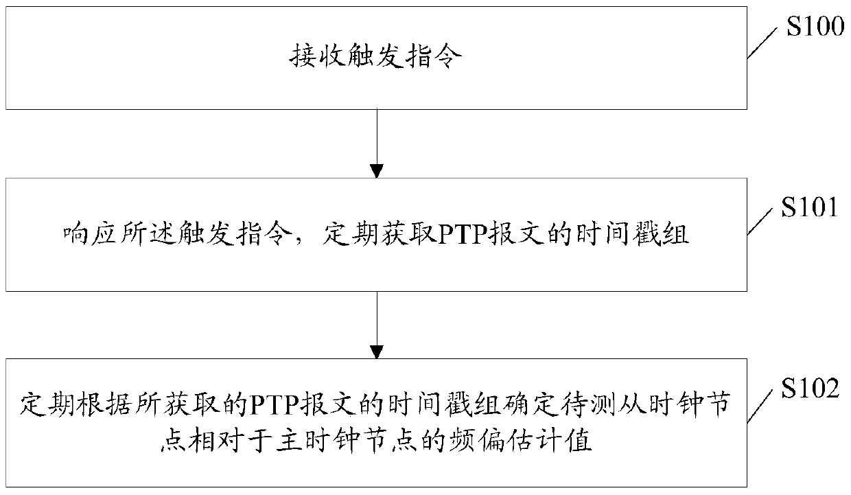
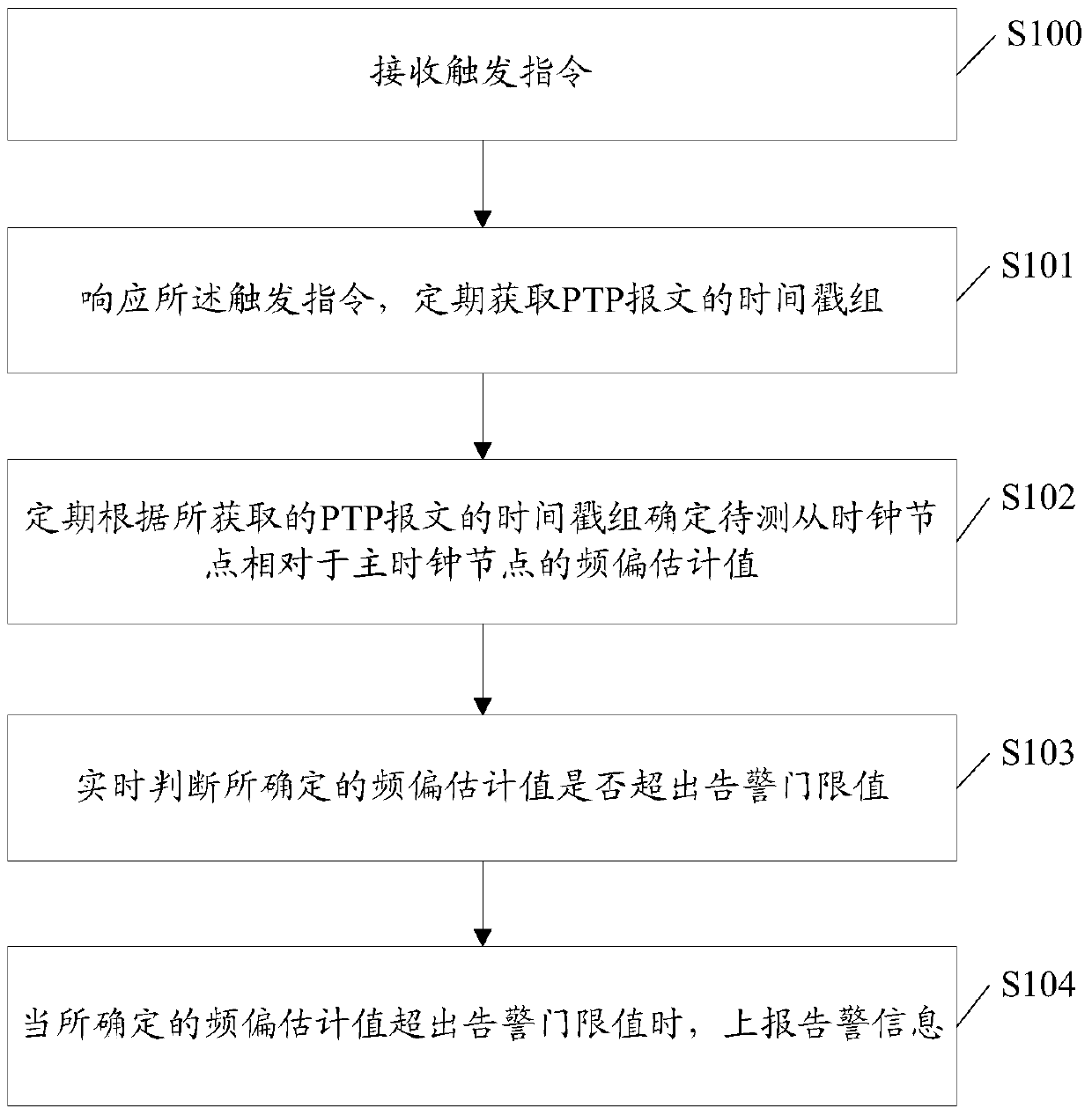
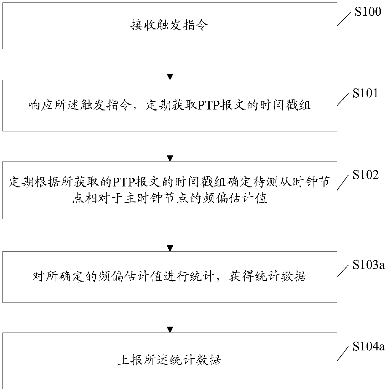
[0045] In the embodiment of the present invention, the slave clock node to be tested receives the trigger instruction; in response to the trigger instruction, periodically obtains the time stamp group of the precision time protocol PTP message; the PTP message is the slave clock node to be tested and the master clock node Messages during the time synchronization process: periodically determine the estimated frequency offset value of the slave clock node to be tested relative to the master clock node according to the time stamp group of the acquired PTP message.

[0046] The present invention will be further described in detail below in conjunction with the accompanying drawings and specific embodiments.

[0047] figure 1 It is a schematic diagram of the implementation process of the frequency offset monitoring method based on the time synchronization network in the embodiment of the present invention Figure 1 ,Such as figure 1 As shown, the frequency offset monitoring metho...


PUM


Abstract

Provided in the present invention are a frequency deviation monitoring method, device and computer storage medium, the method comprising: receiving a triggering instruction; obtaining a timestamp group of a precision time protocol (PTP) message in response to the triggering instruction; determining an estimated frequency deviation value of a to-be-monitored slave clock node with respect to a master clock node according to the timestamp group of the obtained PTP message.

Description

technical field [0001] The invention relates to the field of packet synchronization networks, in particular to a frequency offset monitoring method and device based on a time synchronization network. Background technique [0002] In recent years, with the continuous development of mobile communication technology, the time synchronization network based on the precision clock synchronization protocol standard 1588v2 of the network measurement and control system has been widely used in mobile operators. With the increasing scale of the 1588v2 synchronization network, in order to achieve efficient operation and maintenance of the 1588v2 time synchronization network, it is necessary for the packet-carrying clock node to monitor the packet layer time synchronization and the performance of the internal time module of the clock node in real time. However, the Operation Administration and Maintenance (OAM) system and related technologies based on the time synchronization network are ...

Claims


Application Information

Patent Timeline
Patent Type & Authority Patents(China)
IPC IPC(8): H04L7/00H04W56/00
CPCH04L7/00
Inventor 李春华
Owner 深圳市中兴通讯技术服务有限责任公司
Why Eureka
Try Eureka