Eureka AIR delivers breakthrough ideas for toughest innovation challenges, trusted by R&D personnel around the world.

Rapid time domain analysis method based on second-order multi-edge response method

A time domain analysis, multi-edge technology, applied in special data processing applications, instruments, electrical digital data processing, etc., can solve the problem of driver switching activities not being considered, unable to capture device nonlinear characteristics, etc.

Active Publication Date: 2016-05-11
XIDIAN UNIV
View PDF3 Cites 5 Cited by
  • Summary
  • Abstract
  • Description
  • Claims
  • Application Information

AI Technical Summary

Problems solved by technology

When faced with the asymmetry of the rising and falling sides, although the dual-edge response method for nonlinear drivers will be more accurate than the unit impulse response method, the dual-edge response method cannot capture the nonlinear characteristics of the device, because The switching activity of the drive outside the current bit range is not taken into account

Method used


Image

  • Rapid time domain analysis method based on second-order multi-edge response method
  • Rapid time domain analysis method based on second-order multi-edge response method
  • Rapid time domain analysis method based on second-order multi-edge response method

Examples


Embodiment Construction

[0090] The present invention will be described in detail below in conjunction with the accompanying drawings.

[0091] Refer to attached figure 1 , the implementation steps of the present invention are as follows:

[0092] (1) Read the waveform response

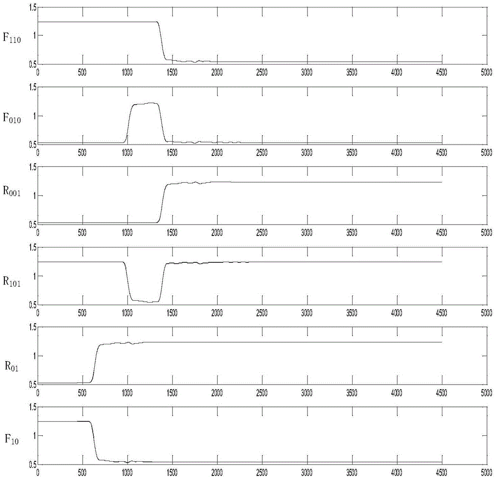
[0093] 1a) The user constructs the corresponding waveform response: the waveform responses constructed by the user are respectively F 110 , F 010 , R 001 , R 101 , the waveform responses when sending the rising and falling edges are R 01 , F 10 , the constructed waveform response is as follows figure 2 shown. Each response constructed by the user should be a function of voltage and time. The waveform response is represented as a row of voltage values ​​at fixed time intervals, and the time length of each constructed response is the same;

[0094] 1b) Read a user-built waveform response:

[0095] (2) Processing waveform response

[0096] 2a) Determine the starting point of the cursor according to the waveform respo...


PUM


Abstract

The invention discloses a rapid time domain analysis method based on a second-order multi-edge response method, and aims to effectively solve a series of problems caused by a non-linear system in maximum distortion analysis. The rapid time domain analysis method comprises the following steps: (1) reading waveform response; (2) processing waveform response; (3) calculating a vector, namely, processing the read waveform response as the vector to be solved; (4) solving the vector, processing the data obtained in a former step into expected data, wherein the step is the core key content of the method; (5) removing a main cursor, and recalculating; (6) acquiring the expected data; (7) acquiring an eye pattern for evaluating the performance of a system. By using the rapid time domain analysis method, the situation in the signal transmission process can be relatively precisely calculated, problems of a conventional method can be avoided, and the problem of signal integrity in practical application can be relatively well solved. The rapid time domain analysis method can be popularized to a relatively high-class multi-edge response method, and thus the multi-edge response method can be systematically used in engineering practice.

Description

technical field [0001] The method belongs to the field of signal integrity, and further relates to a fast time-domain analysis method for high-speed circuits based on a second-order multi-edge response method. This method can be applied to the design and analysis of signal integrity in high-speed circuits. Background technique [0002] With the development of high-speed and high-density semiconductor technology, high-speed circuit and system design technology, which is the core competitiveness, has become an essential weapon. The analysis and modeling of passive channels is and will continue to be the primary task of signal integrity engineers, so it is very important to be able to quickly calculate the maximum distortion of signal transmission in the channel. Generally, the waveform data is read in the time domain to calculate the maximum distortion of signal transmission to improve the design. In this process, the most critical issue is to use a certain method to quickly ...

Claims


Application Information

Patent Timeline
Patent Type & Authority Applications(China)
IPC IPC(8): G06F17/50
CPCG06F30/398
Inventor 初秀琴王卓超周子翔李亚婷徐志华严锦荣姜丰
Owner XIDIAN UNIV
Why Eureka
Eureka Blog
Learn More