
Self-supporting pre-stress combination beam lightweight aggregate concrete composite slab

A technology of concrete and composite beams, applied in floors, building components, buildings, etc., can solve the problems of heavy weight of prefabricated concrete components, affecting the promotion and application of structural systems, and high cost of steel component projects

Inactive Publication Date: 2016-05-11
QIQIHAR UNIVERSITY
View PDF8 Cites 7 Cited by
  • Summary
  • Abstract
  • Description
  • Claims
  • Application Information

AI Technical Summary

Problems solved by technology

[0003] 1. The disadvantages of cast-in-place integral floors are that the formwork materials are too much, the construction wet work is heavy, the speed is slow, and the construction period is long
[0004] 2. Assembled monolithic concrete floors have poor structural integrity and poor seismic performance, and it is difficult to ensure that component nodes are rigid nodes, which will seriously affect the promotion and application of this structural system
[0005] 3. Ordinary assembled monolithic concrete floors are difficult to adapt to large-span space structures due to the heavy weight of prefabricated concrete components involved. When using combined steel structures, it involves poor overall and local stability of steel components, and shear forces between steel structures and concrete. The disadvantages of steel components and cast-in-place concrete structures, such as the inability to ensure the coordination of the deformation of steel components and the high cost of steel components, limit the application of this type of structure.

Method used


Image

  • Self-supporting pre-stress combination beam lightweight aggregate concrete composite slab
  • Self-supporting pre-stress combination beam lightweight aggregate concrete composite slab
  • Self-supporting pre-stress combination beam lightweight aggregate concrete composite slab

Examples


Embodiment Construction

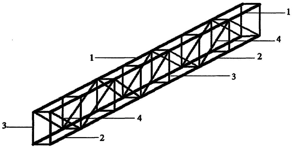
[0013] 1. Made steel trusses ( figure 1 ), to ensure the strength, stiffness and stability of the truss structure, the specific implementation process is as follows:

[0014] A. Binding welded beams and steel bar trusses, the height of the skeleton is the height of the floor slab after removing the thickness of the upper and lower protective layers;

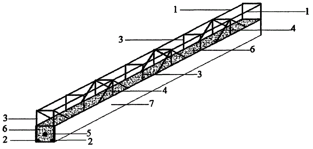
[0015] B Laying and tensioning of prestressed tendons, the position of which is the center of the concrete section of the beam;

[0016] C Concrete is poured in the prefabricated formwork, and the steel bars at the bottom of the beam have no protective layer;

[0017] D When the concrete reaches the design strength, stretch the prestressed tendons to form a prestressed concrete beam ( figure 2 );

[0018] 2. Made a lightweight aggregate concrete laminated slab ( image 3 ), the specific implementation process is as follows:

[0019] A Lay the prefabricated composite slab reinforcement, install the prestressed composite beam...


PUM


Abstract

The invention relates to a self-supporting pre-stress combination beam composite lightweight aggregate concrete formwork system, comprising manufacturing of a pre-tensioned pre-stressing steel bar truss-concrete combined beam and manufacturing of prefabricated composite slabs. The manufacturing of a pre-tensioned pre-stressing steel bar comprises steps: 1,binding and welding a beam steel bar truss, a framework height being height of a floor slab subtracting thickness of an upper protection layer and a lower protection layer, a beam top and a bottom steel bar being not provided with a protection layer; 2, laying and tensioning a pre-stressed bar, the position of the pre-stressed bar being the center of the section of beam concrete; 3, pouring concrete in a prefabricated form; 4, after the concrete reaches design strength, relaxing the pre-stressed bar, to form a pre-stressing steel bar-concrete combined beam; 5, laying prefabricated composite slab steel bars, installing a pre-stressed beam on the composite slab steel bars according to design, and connecting the pre-stressed beam with plate steel bars; 6, pouring a lightweight aggregate concrete composite slab, to form the self-supporting pre-stress combination beam composite lightweight aggregate concrete formwork.

Description

technical field [0001] The patent of the present invention provides a self-supporting prestressed composite beam laminated lightweight aggregate concrete laminated slab for assembling an integral structure laminated floor structure. Background technique [0002] At present, the concrete floor structure can be divided into three types: cast-in-place integral type, prefabricated type and assembled integral type according to the construction method. One is the cast-in-place integral floor, which has good integrity by installing steel bars in the formwork and pouring concrete. The second is the prefabricated concrete floor, which is a floor structure system composed of prefabricated beams and slabs. It has fast construction speed, is convenient for industrial production and mechanized construction, and saves labor. The third is to assemble the integral concrete floor, which installs the components of various prefabricated parts in place, and makes it an integral structure throu...

Claims


Application Information

Patent Timeline
IPC IPC(8): E04B5/23
Inventor 张道明陈秀洁郭国梁
Owner QIQIHAR UNIVERSITY
Learn More