Filtering device for particle oil in printing and dyeing aqueous liquid

A technology of granular oil and printing and dyeing water, applied in filtration treatment, grease/oily substance/float removal device, textile industry wastewater treatment, etc. To achieve the effect of good degreasing effect, convenient replacement and lower maintenance cost

Active Publication Date: 2016-05-11
福思南纺织(常熟)有限公司
View PDF5 Cites 7 Cited by
  • Summary
  • Abstract
  • Description
  • Claims
  • Application Information

AI Technical Summary

Problems solved by technology

[0002] The existing printing and dyeing sewage particle filtration method generally uses an intermediate filter screen to filter the particulate matter in the sewage. However, the existing filter screen is generally fixed on the frame frame, and the screen plate It cannot be replaced individually, but can only be replaced collectively, which is very troublesome and the existing filter devices generally only filter once, and the effect is not ideal
[0003] However, the existing printing and dyeing sewage degreasing and filtering method generally adopts the principle that an upper partition and a lower partition are arranged in the box, and the oil floats on the water surface through the flow of water, so that the water at the bottom flows, and the upper part The oil is blocked by the upper partition to remove the oil, and then the oil floating on the water is manually removed, the effect is not ideal, and the degree of automation is poor

Method used


Image

  • Filtering device for particle oil in printing and dyeing aqueous liquid
  • Filtering device for particle oil in printing and dyeing aqueous liquid
  • Filtering device for particle oil in printing and dyeing aqueous liquid

Examples


Embodiment Construction

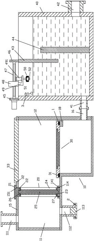
[0028] Examples, see e.g. Figure 1 to Figure 5 As shown, a printing and dyeing water particle oil filter device includes a filter box 10 and an oil removal filter box 40, and the filter box 10 includes a left filter box 11 and a right filter box 12, and the right filter The bottom plate of the box body part 12 is lower than the bottom plate of the left filter box body part 11, and the upper part of the filter box body 10 is fixed with an upper plate body 15, and the upper part of the upper plate body 15 is connected with a liquid inlet pipe at the upper part of the left filter box body part 11 111, the bottom plate of the left filter box body 11 is connected with a particle discharge pipe 112, and the bottom end of the particle discharge pipe 112 is fixed with a plug 113;

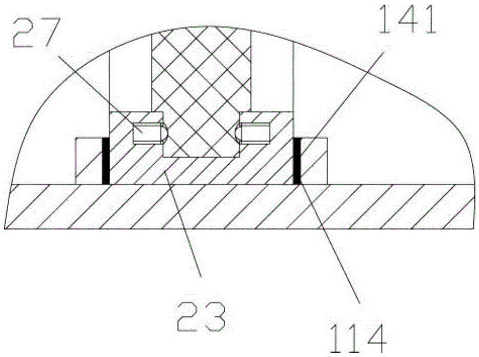
[0029] There is a slot 14 on the bottom plate at the right end of the left filter box body part 11, and the upper plate body 15 just above the slot 14 has a vertical jack 151, and the first filter screen p...


PUM


Abstract

The invention discloses a filtering device for particle oil in printing and dyeing aqueous liquid. The filtering device comprises a filtering tank and an oil removal filtering tank; the filtering tank comprises a left filtering tank part and a right filtering tank part; a bottom plate of the right filtering tank part is lower than a bottom plate of the left filtering tank part; the upper part of the filtering tank is fixedly provided with an upper plate body; the upper part, located at the left filtering tank part, of the upper plate body communicates with a liquid inlet pipe; the bottom plate of the left filtering tank part communicates with a particle discharge pipe; the bottom end of the particle discharge pipe is fixedly provided with a plug; the lower part of the right end face of the right filtering tank part communicates with a liquid outlet pipe; the lower part of a left side plate of the oil removal filtering tank communicates with an oil removal liquid inlet pipe; the oil removal liquid inlet pipe communicates with a liquid outlet pipe; the top face of the left side plate of the oil removal filtering tank is fixedly provided with an oil removal support plate; the top face of an upper partition plate is fixedly provided with an upper oil removal support plate. As multiple filtering is adopted, the filtering device has a good filtering effect; moreover, the filtering device can automatically accumulate and remove the oil in waste water without manual fishing out, and has a good oil removal effect.

Description

Technical field: [0001] The invention relates to the technical field of printing and dyeing environmental protection equipment, in particular to a printing and dyeing water particle oil filter device. Background technique: [0002] The existing printing and dyeing sewage particle filtration method generally uses an intermediate filter screen to filter the particulate matter in the sewage. However, the existing filter screen is generally fixed on the frame frame, and the screen plate They cannot be replaced individually, but can only be replaced collectively, which is very troublesome and the existing filter devices generally perform single-time filtration, and the effect is not ideal. [0003] However, the existing printing and dyeing sewage degreasing and filtering method generally adopts the principle that an upper partition and a lower partition are arranged in the box, and the oil floats on the water surface through the flow of water, so that the water at the bottom flow...

Claims


Application Information

Patent Timeline
Patent Type & Authority Applications(China)
IPC IPC(8): C02F9/02C02F103/30
CPCC02F1/001C02F1/40C02F9/00C02F2103/30
Inventor 谭儒峰
Owner 福思南纺织(常熟)有限公司
Why Eureka
Try Eureka