A kind of polishing equipment for smt laser template

A laser template and equipment technology, applied in grinding/polishing equipment, metal processing equipment, machine tools for surface polishing, etc., can solve the problems of increasing production costs, large amount of polishing liquid used, etc., to reduce the amount of use and reduce production costs , easy to use effect

Active Publication Date: 2017-09-08
宿州市徽腾知识产权咨询有限公司
View PDF6 Cites 0 Cited by
  • Summary
  • Abstract
  • Description
  • Claims
  • Application Information

AI Technical Summary

Problems solved by technology

The existing method of polishing SMT laser templates generally adopts the chemical immersion method. During the polishing process, it is only necessary to inject the polishing solution into the container, and then pour the laser template to be polished into the polishing solution. The polishing process is relatively simple. However, its disadvantages are: during the polishing process, a large amount of polishing liquid needs to be injected into the container to submerge the laser template, and the amount of polishing liquid used is relatively large, which increases the production cost

Method used


Image

  • A kind of polishing equipment for smt laser template
  • A kind of polishing equipment for smt laser template
  • A kind of polishing equipment for smt laser template

Examples


Embodiment

[0029] Embodiment: The embodiment of the present invention is illustrated by specific specific examples below. Those skilled in the art can easily understand other advantages and effects of the present invention from the contents disclosed in this specification. The descriptions "below", "top", "bottom", etc. are defined in the usual sense, e.g., with reference to the definition of the direction of gravity, the direction of gravity is below, the opposite direction is above, similarly above is top Or the top, below is the bottom or the bottom, which is only for the convenience of description, but not to limit the scope of the present invention. The change or adjustment of its relative relationship should also be regarded as no substantial change in the technical content. It is the scope in which the present invention can be implemented.

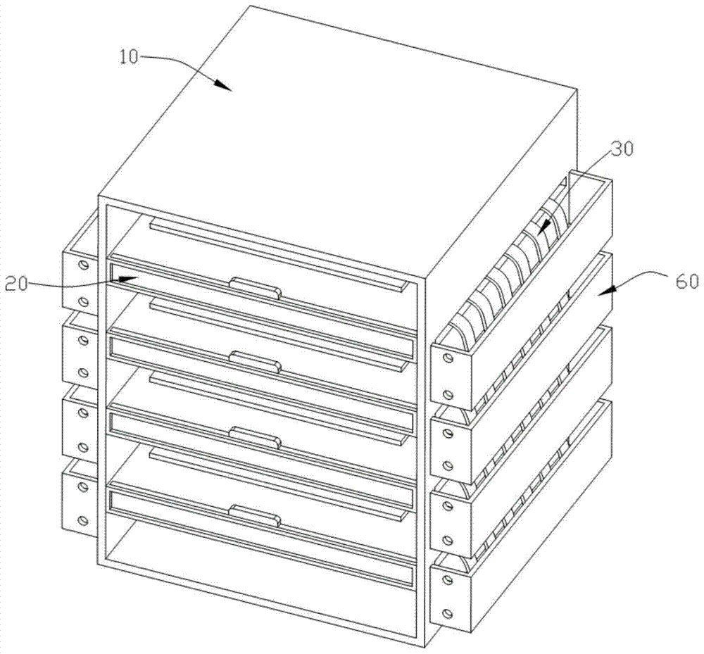
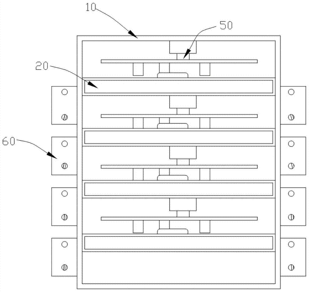
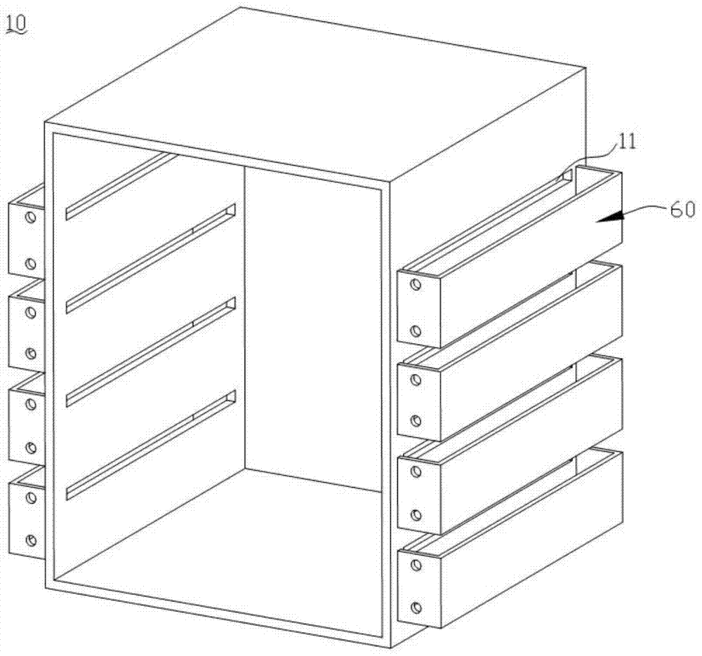
[0030] See Figure 1 to Figure 5 As shown, a polishing device for SMT laser templates includes: a housing 10 with a hollow cavity and an ope...


PUM


Abstract

The invention discloses polishing equipment for surface mounting technology (SMT) laser templates. The polishing equipment comprises a housing, a plurality of polishing chambers, solution supply units, fiber sleeves and cylinder units, wherein a plurality of first through grooves distributed at equal intervals in the height direction are formed in a pair of opposite side walls of the housing; the polishing chambers are mounted in the housing and distributed at equal intervals in the height direction of the housing, each polishing chamber comprises a box body and a cover plate, and second through grooves opposite to the corresponding first through grooves are formed in a pair of opposite side walls of each box body; the solution supply units are mounted on the outer side walls of the housing, located under the first through grooves and used for supplying polishing solutions to the laser templates; the laser templates are sleeved with the fiber sleeves which are used for guiding the polishing solutions in the solution supply units to the laser templates; the cylinder units are mounted in the housing and located over the corresponding polishing chambers; a plurality of through holes corresponding to hole portions of the laser templates are formed in the top end faces of the polishing chambers and the top end faces of the fiber sleeves. According to the polishing equipment, the usage amount of the polishing solutions can be reduced effectively, and production cost is lowered.

Description

[0001] Technical field: [0002] The invention relates to the technical field of polishing equipment, in particular to a polishing equipment for SMT laser templates. [0003] Background technique: [0004] Surface mount technology (SMT) is currently the mainstream technology for electronic product manufacturing. Printing stencils are required before the electronic component placement process. The printing stencils are produced by chemical etching and laser cutting. Laser-cut stencils are usually called SMT laser stencils, which have the characteristics of high position accuracy, but there are certain burrs and roughness on the outer surface and hole wall after cutting, which will affect the effect of printing solder paste. Since SMT laser templates are generally thinner and their holes are smaller, common methods of deburring and polishing, such as mechanical grinding, are not applicable. The existing method of polishing SMT laser templates generally adopts the chemical immer...

Claims


Application Information

Patent Timeline
Patent Type & Authority Patents(China)
IPC IPC(8): B24B29/02B24B57/02
CPCB24B29/02B24B57/02
Inventor 高扬
Owner 宿州市徽腾知识产权咨询有限公司
Why Eureka
Try Eureka