
Electromagnetic shielding method for communication equipment and communication equipment with electromagnetic shielding function

A technology of electromagnetic shielding and communication equipment, applied in the direction of magnetic/electric field shielding, electrical components, gaskets/seals, etc., to achieve good electrical contact performance, reduce electromagnetic leakage, and good sealing and shielding effects

Inactive Publication Date: 2016-05-04
莫镇威
View PDF8 Cites 7 Cited by
  • Summary
  • Abstract
  • Description
  • Claims
  • Application Information

AI Technical Summary

Problems solved by technology

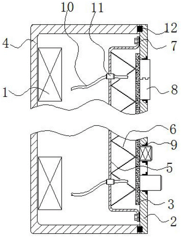
[0003] In view of the above deficiencies, the purpose of the present invention is to provide a method for electromagnetic shielding of communication equipment, through the cooperation of the communication chassis body and the equipment control panel, a fully enclosed electromagnetic shielding structure is adopted, and a wire mesh and a free type are adopted. Electromagnetic shielding gaskets, rings, and sleeves of conductive particles can shield most of the electromagnetic field, and also set up a clever heat dissipation structure, so there is no problem of poor heat dissipation

Method used


Image

  • Electromagnetic shielding method for communication equipment and communication equipment with electromagnetic shielding function
  • Electromagnetic shielding method for communication equipment and communication equipment with electromagnetic shielding function
  • Electromagnetic shielding method for communication equipment and communication equipment with electromagnetic shielding function

Examples


Embodiment 1

[0052] see Figures 1 to 3 The electromagnetic shielding method for communication equipment provided in this embodiment includes the following steps:

[0053] A communication device body 1 is provided, the communication device body includes a control panel, and the control panel includes an alloy liner 2 and a circuit board 3 disposed inside the alloy liner 2;

[0054] A case body 4 for installing the communication device body 1 is provided, and the case body 4 is a square box with an opening on one side;

[0055] A shielding cover 5 is arranged inside the alloy liner 2, and the shielding cover 5 completely covers the circuit board 3; the shielding cover 5 is an aluminum alloy member with a U-shaped cross section;

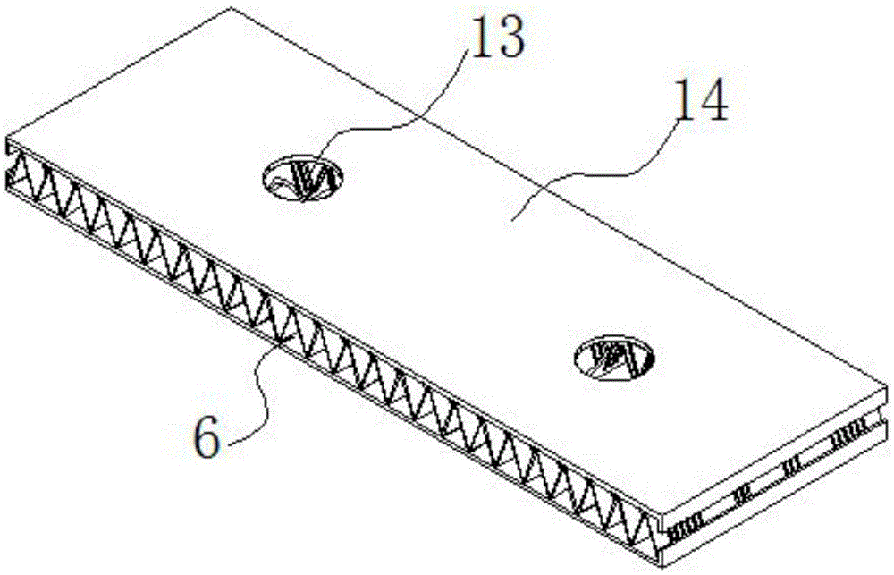
[0056] A cooling fin 6 is arranged between the shielding cover 5 and the circuit board 3, and the surface of the cooling fin 6 is covered with a thermally conductive insulating coating (the thermally conductive insulating coating is formed by a common thermally co...

Embodiment 2

[0089] Embodiment 2 is basically the same as Embodiment 1, except that it is an extra-large communication device with a large heat dissipation. The heat sink 6 is folded in a wave shape, and the cross section formed by it is V-shaped or inverted V-shaped. A heat dissipation pipe is provided in the space, and a thermal fluid is provided in the heat dissipation pipe. The heat dissipation pipe passes through the shielding cover, and The outer side of the cover is coiled, and a tubular capacitor is arranged between the heat dissipation pipe and the shielding cover.

Embodiment 3

[0091] Embodiment 3 is basically the same as Embodiment 1, and its difference is:

[0092] A preparation method for an electromagnetic shielding sealing strip, an electromagnetic shielding gasket, and an electromagnetic shielding sealing sleeve comprises the following steps:

[0093] 1) Prepare the following components in parts by weight:

[0094]

[0095] Wherein, the silicone rubber is methyl vinyl silicone rubber; the curing agent is trimethylhexamethylenediamine; and the thermal stabilizer is epoxy fatty acid methyl ester.

[0096] 2) After heating and melting the silicone rubber and polytetrafluoroethylene, add nano-scale graphite powder, and stir for 10 minutes under the action of high-speed stirring to make it evenly mixed and dispersed; then add curing agent and heat stabilizer, and stir in the same way to make It is uniformly dispersed to form a composite rubber mixture in a molten state uniformly infiltrated with nano-scale graphite particles.

[0097] 3) Prepar...


PUM

PropertyMeasurementUnit
diameteraaaaaaaaaa
diameteraaaaaaaaaa
diameteraaaaaaaaaa

Abstract

The invention discloses an electromagnetic shielding method for communication equipment. According to the electromagnetic shielding method, a communication equipment body is provided, wherein the communication equipment body comprises a control panel; the control panel comprises an alloy lining plate and a circuit board; a machine case body for installing the communication equipment body is arranged; a shielding case is arranged at the inner side of the alloy lining plate and completely covers the circuit board; a cooling fin coated with a heat-conducting insulated coating is arranged between the shielding case and the circuit board; the cooling fin is arranged in a folding manner in a wave shape; the upper side of the cooling fin is in contact with the circuit board; the lower side of the cooling fin is in contact with the shielding case; electromagnetic shielding gaskets are arranged between the edge part of the shielding case and the alloy lining plate; a faucet is arranged on the circuit board; an electromagnetic shielding seal sleeve is arranged between the faucet and the alloy lining plate; cables are arranged on the circuit board; feed-through capacitors are arranged between the cables and the shielding case; the cables pass through the shielding case through the feed-through capacitors and are connected with electronic components; the alloy lining plate is fastened to an open side of the machine case body; and electromagnetic shielding seal strips are arranged on the fastened parts. The invention further discloses the communication equipment with the electromagnetic shielding function.

Description

technical field [0001] The invention relates to electromagnetic shielding of communication equipment, in particular to an electromagnetic shielding method of communication equipment and communication equipment with electromagnetic shielding function. Background technique [0002] Whether the overall electromagnetic shielding performance of the communication equipment is good or not usually depends on whether the electromagnetic shielding structure design of the chassis is reasonable, whether it is perfectly matched with the communication equipment itself, and the main part of the communication equipment is fully electromagnetically shielded, while the control panel of the communication equipment and The circuit board corresponding to the control panel is one of the main parts. Traditional chassis used in communication equipment, although the design of the structure and layout of the box body is very good, and each area is orderly, but its electromagnetic shielding still need...

Claims


Application Information

Patent Timeline
Patent Type & Authority Applications(China)
IPC IPC(8): H05K9/00C08L83/07C08L27/18C08K3/04
CPCH05K9/0015C08K2201/011C08L83/04C08L2203/20H05K9/0081
Inventor 莫镇威
Owner 莫镇威
Learn More