
Underwater communication system

An underwater communication and subsystem technology, applied in transmission systems, digital transmission systems, electromagnetic wave transmission systems, etc., can solve the problems of different beam absorption and attenuation, short transmission distance, etc., to reduce the bit error rate and reduce system power consumption Effect

Inactive Publication Date: 2016-05-04
OCEAN UNIV OF CHINA
View PDF1 Cites 43 Cited by
  • Summary
  • Abstract
  • Description
  • Claims
  • Application Information

AI Technical Summary

Problems solved by technology

Moreover, in the shallow sea area and the deep sea area, the turbidity of the sea water is different, and the absorption and attenuation effects on the light beam are also different. The minimum attenuation coefficient band of ocean water is 480-500nm, and the minimum attenuation coefficient band of coastal sea water is 530-580nm. It can be seen that , the best window of the beam in seawater only exists in the 480-580nm band, and the transmission distance is much shorter than that of the sound wave
[0005] Obviously, the current underwater communication system for a single transmission medium can no longer meet the current needs of people for underwater fast communication. In addition, in the prior art, only one modulation and demodulation method is used for one communication method, so it cannot be based on the underwater communication system. Under the conditions to give full play to the respective advantages of underwater acoustic communication and wireless optical communication

Method used

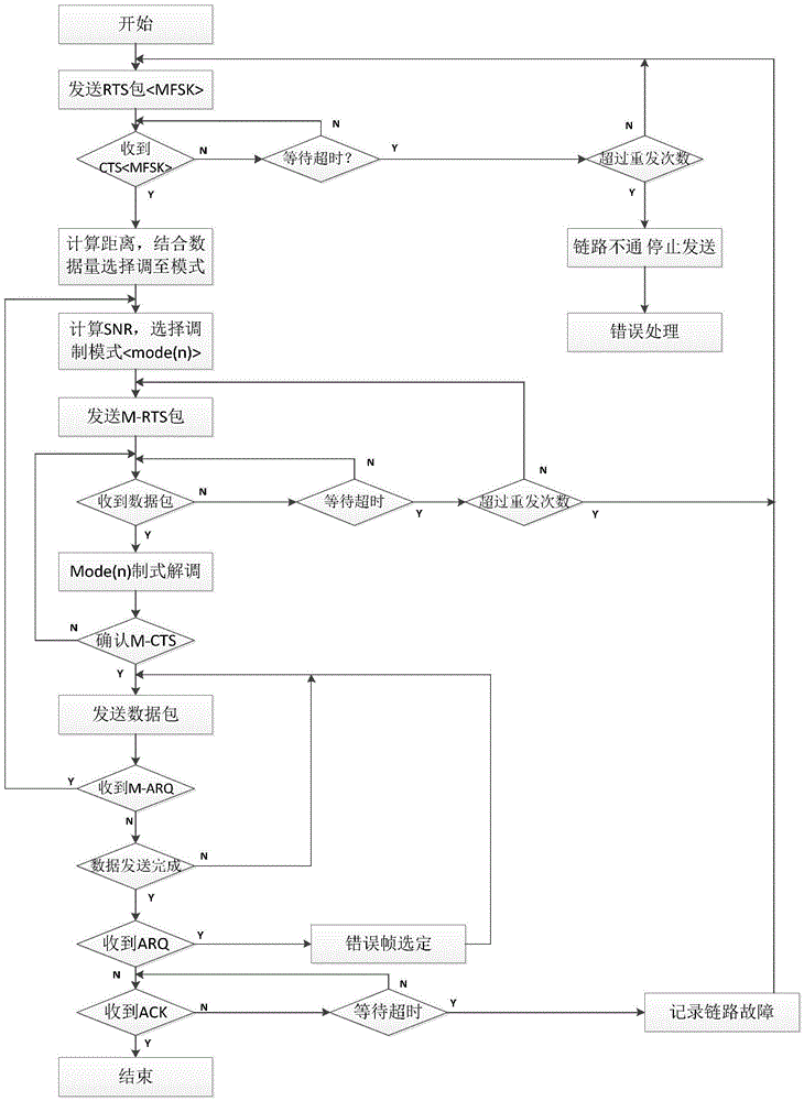
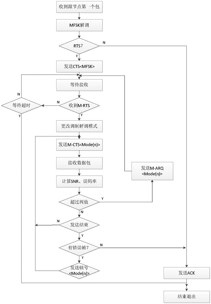

Image

  • Underwater communication system
  • Underwater communication system
  • Underwater communication system

Examples


Embodiment Construction

[0042] In order to facilitate a further understanding of the present invention, the technical solutions of the present invention will be further explained below in conjunction with the drawings and specific embodiments, and each embodiment does not constitute a limitation to the embodiments of the present invention.

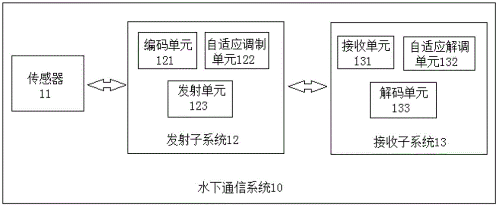
[0043] According to an embodiment of the present invention, a multi-mode adaptive underwater communication system 10 based on software radio technology is provided, such as figure 1 As shown, the system 10 includes a sensor 11, a transmitting subsystem 12 and a receiving subsystem 13, wherein the sensor 11 is used for sensing the external environment, such as sensing the depth of water, the complexity of the environment, channel conditions, the size of data transmission, And the distance of reliable communication helps the underwater wireless communication node to automatically select the appropriate communication mode (underwater acoustic or wireless optical comm...


PUM


Abstract

The invention relates to an underwater communication system. The underwater communication system comprises a sensor, a transmitting sub-system and a receiving sub-system, wherein the sensor is used for sensing an external environment, and assisting an underwater wireless communication node in automatically selecting a proper communication mode and a corresponding modulation-demodulation mode; the transmitting sub-system consists of an encoding unit, an adaptive modulation unit and an transmitting unit; the transmitting sub-system is used for transmitting a signal to be transmitted to a corresponding channel of the transmitting unit after the signal is encoded by the encoding unit and demodulated by the adaptive modulation unit, and converting an electric signal into an acoustic signal or an optical signal to transmit the acoustic signal or the optical signal; the receiving sub-system consists of a receiving unit, an adaptive demodulation unit and a decoding unit; and after a corresponding channel of the receiving unit receives the acoustic signal or the optical signal and converts the acoustic signal or the optical signal into the electric signal, the electric signal is demodulated by the adaptive demodulation unit, and an original signal is demodulated by a decoder of the decoding unit lastly. Through adoption of the underwater communication system, reliable transmission of data or instructions within a communication network range is realized.

Description

technical field [0001] The invention relates to the field of underwater communication, in particular to an underwater communication system. Background technique [0002] At present, with the continuous development of underwater applications such as communication, exploration, and monitoring, the use of large-volume sensing devices represented by sensors such as video and sonar is becoming more and more frequent. The requirements of the system are also becoming more and more urgent. However, due to the complexity of the underwater environment, underwater wireless communication (sound and light) channels are different in different waters, different water depths, different transmission distances, horizontal and vertical directions, and the transmission media such as sound and light are different in the underwater environment. The speed, available frequency, and transmission distance are also very different. Therefore, the current underwater wireless communication is still domi...

Claims


Application Information

Patent Timeline
IPC IPC(8): H04B13/02H04B10/548H04L1/00H04L1/16H04L1/18
CPCH04B13/02H04B10/548H04L1/0003H04L1/0006H04L1/1607H04L1/1864
Inventor 丛艳平孙哲殷波魏志强
Owner OCEAN UNIV OF CHINA
Learn More