Hollow cathode power converter and control system thereof

A power converter, hollow cathode technology, applied in the direction of converting AC power input to DC power output, electrical components, output power conversion devices, etc., can solve the time delay of heating power output power, complex design, low efficiency and other problems , to achieve the effect of improving the dynamic response of the power supply, the power density and the total efficiency.

Active Publication Date: 2016-05-04
SHENZHEN ACAD OF AEROSPACE TECH
View PDF2 Cites 12 Cited by
  • Summary
  • Abstract
  • Description
  • Claims
  • Application Information

AI Technical Summary

Problems solved by technology

[0004] Description of existing technical problems and defects: At present, most power supplies for hollow cathodes are designed as independent heating power supply, ignition power supply and contact power supply to realize power supply to hollow cathodes. After the components are all started and working stably, the electric propulsion control system is used to judge the working status of the electric propulsion engine, and then send instructions to turn off the heating power supply, ignition power supply and touch power supply, which greatly delays the ignition success and reduces the output of the heating power supply. power time, which seriously affects the service life of the hollow cathode
In addition, the existing method of three independent power supplies powering the hollow cathode has disadvantages such as power supply volume, weight, low efficiency, and complicated design.

Method used


Image

  • Hollow cathode power converter and control system thereof
  • Hollow cathode power converter and control system thereof
  • Hollow cathode power converter and control system thereof

Examples


Embodiment 1

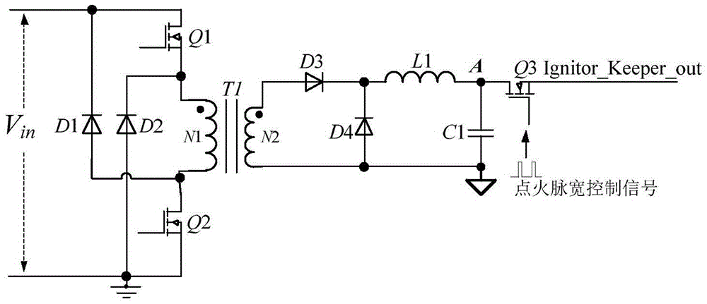
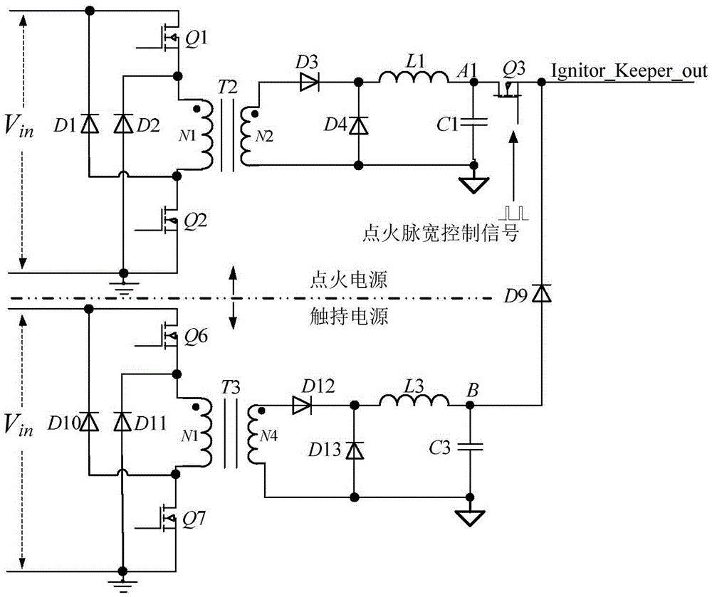
[0034] Such as figure 1 with Figure 6 As shown, this example provides a hollow cathode power converter, including: the main transformer primary circuit and the main transformer secondary rectification and filtering circuit; the main transformer secondary rectification and filtering circuit includes two outputs: heating power output and ignition contact power Output: Sampling the output voltage of the heating power supply of the rectification and filtering circuit on the secondary side of the main transformer to form a closed-loop control of the output voltage, and separately sampling the output current of the heating power supply and the output current of the ignition contact power supply to form a corresponding closed-loop control of the output current loop; in the hollow Before the cathode is successfully ignited, the contact pole and the reference ground present high impedance, the output current loop of the heating power supply works in a closed loop, and the output curr...

Embodiment 2

[0044] Such as Figure 5 As shown, the transformer secondary side rectification filter circuit in this example also includes a heating power supply, the heating power supply includes a diode D5, a diode D6, an inductor L2 and a capacitor C2, and the second end of the secondary side of the transformer T1 with the same name is respectively connected to the The cathode of the diode D6 is connected to one end of the capacitor C2, the second opposite end of the secondary side of the transformer T1 is connected to the cathode of the diode D5, and the anode of the diode D5 and the anode of the diode D6 are respectively grounded through the inductor L2 , the other end of the capacitor C2 is grounded; the output rectification part of the ignition contact power supply is superimposed on the output rectification part of the heating power supply, and the output rectification part of the ignition contact power supply and the output rectification part of the heating circuit adopt the same gr...

Embodiment 3

[0056] This example also provides a control system for a hollow cathode power supply, which includes the hollow cathode power converter described in Embodiment 1 or Embodiment 2, and includes an ignition control circuit 1, a sampling circuit 2 and an ignition variable chopping pulse width Control circuit: the main transformer primary side circuit is connected with the ignition control circuit 1, the ignition control circuit 1 is connected with the main transformer secondary side rectification filter circuit through the sampling circuit 2, and the ignition variable chopping pulse width The control circuit is connected with the rectifying and filtering circuit on the secondary side of the main transformer. Preferably, the ignition variable chopping pulse width control circuit is connected with the secondary rectification and filtering circuit of the main transformer and a chopping switch.

[0057] Such as Figure 10 As shown, the sampling circuit described in this example inclu...


PUM


Abstract

The invention provides a hollow cathode power converter and a control system thereof. The hollow cathode power converter comprises a main transformer primary side circuit and a main transformer auxiliary side rectifying and wave-filtering circuit; the output voltage of the main transformer auxiliary side rectifying and wave-filtering circuit is sampled to form voltage closed-loop control, and the output current of the main transformer auxiliary side rectifying and wave-filtering circuit is sampled to form output current closed-loop control; before the ignition of a hollow cathode is successful, a holding electrode and reference ground present high impedance, and a current closed-loop does not work; when the ignition of the hollow cathode is successful, the impedance of the holding electrode is decreased until the output voltage of the main transformer auxiliary side rectifying and wave-filtering circuit is dragged to be lower than a second set value so as to judge that the ignition of the hollow cathode is successful; and when the voltage of the holding electrode is decreased to be lower than the maximum limiting voltage of a holding power supply, closed-loop control is carried out on the output current of the main transformer auxiliary side rectifying and wave-filtering circuit. A heating power supply, an ignition power supply and the holding power supply are coupled to obtain a main converter, so that the power density is high, and the dynamic response is improved.

Description

technical field [0001] The invention relates to a power control circuit, in particular to a hollow cathode power converter and a control system including the hollow cathode power converter. Background technique [0002] The traditional hollow cathode power supply is composed of three power supplies: cathode heating power supply, cathode ignition power supply and cathode contact power supply. The power supply is referred to as the ignition power supply, and the cathode touch power supply is referred to as the touch power supply; the hollow cathode power supply is a power supply for the hollow cathode device. The heating power supplies power to the heater of the hollow cathode, the ignition power supply and the contact power supply are connected to the contact electrode of the hollow cathode at the same time, and provides high-voltage pulse voltage for ignition and contact current to maintain the ignition state for the contact electrode, and the heating power supply , the ign...

Claims


Application Information

Patent Timeline
Patent Type & Authority Applications(China)
IPC IPC(8): H02M7/217H03K7/08
CPCH02M7/217H03K7/08
Inventor 付明张贤涛
Owner SHENZHEN ACAD OF AEROSPACE TECH
Why Eureka
Try Eureka