
A method and device for image mapping transformation based on multi-lens and multi-sensor

A mapping transformation, multi-sensor technology, applied in the field of image processing, can solve the problems of difficult to support the simultaneous processing of data from multiple lenses, the storage of the mapping table occupies a large amount of storage resources, and the usage of storage resources is large. Improve real-time, improve the effect of timeliness

Active Publication Date: 2019-02-12
GUANGZHOU SHENGGUANG MICROELECTRONICS
View PDF4 Cites 0 Cited by
  • Summary
  • Abstract
  • Description
  • Claims
  • Application Information

AI Technical Summary

Problems solved by technology

[0004] The image mapping transformation in the prior art still has the following disadvantages: the transformation coordinate relationship is generated through the projection transformation matrix, and the image is directly calculated and processed by using the coordinate relationship, which has a large amount of calculation, a long operation time, and a large power consumption; the existing mapping transformation has a large impact on the image The mapping position and deformation are limited; the existing mapping transformation is realized by FPGA hardware, the storage of the mapping table takes up a lot of storage resources, and the buffer storage of the input image and the output image also takes up a lot of storage resources, and a large amount of data is stored in The storage waits for the mapping relationship to be satisfied before processing, and the real-time performance is not high; the storage resource usage is large, and it is difficult to support the data of multiple lenses to be processed at the same time

Method used


Image

  • A method and device for image mapping transformation based on multi-lens and multi-sensor
  • A method and device for image mapping transformation based on multi-lens and multi-sensor
  • A method and device for image mapping transformation based on multi-lens and multi-sensor

Examples


Embodiment Construction

[0061] The specific embodiment of the present invention will be further described below in conjunction with accompanying drawing

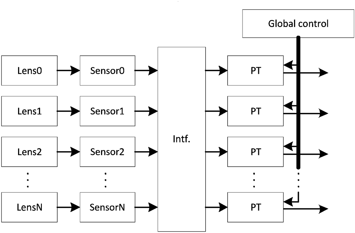
[0062] Such as Figure 1-Figure 6 Shown, a kind of image mapping transformation device based on multi-lens multi-sensor, comprises lens (Lens) group, sensor (Sensor) module and image processing module, and described image processing module comprises data interface (intf.), projective transformation module again (PT) and global control module (Global control); where:

[0063] The lens group includes at least one lens, the position of each lens is arbitrary, and each lens has a common coverage area with at least one of the other lenses;

[0064] The sensor module is used to convert the light signal reflected by the target object into an electrical signal, and the sensor module includes a plurality of sensors;

[0065] The data interface is used to transmit the data of a single lens to the projection transformation module or to mix and transmit the ...


PUM


Abstract

The invention discloses an image mapping transformation device based on multi-lens and multi-sensor, which includes a lens group, a sensor module and an image processing module. The image processing module further includes a data interface, a projection transformation module and a global control module; the lens group includes at least A lens; the sensor module is used to convert the optical signal reflected by the target object into an electrical signal; the data interface is used to transmit the data of at least one lens to the projection transformation module or convert the data of each lens into a unified clock domain; the projection transformation module is used to process data from at least one lens and sensor; the global control module is used to perform global control processing on each projection transformation module. The image mapping transformation of the present invention includes image transformation and image mapping, which simplifies the complexity of transformation and mapping, reduces the amount of calculation, improves timeliness, and reduces power consumption; multiple lens mapping transformations are processed simultaneously, and multiple imaging unit data multiplexing processing is supported. .

Description

technical field [0001] The invention relates to the field of image processing, and specifically relates to an image mapping transformation method and device based on multi-lens and multi-sensor. Background technique [0002] An image map is a graphic or text box that responds to link indications. Clicking on a defined area of ​​the graphic or text box will take you to the target linked to that area. [0003] Image transformation refers to the two-dimensional linear reversible transformation of the original image by using an orthogonal function or an orthogonal matrix to represent the image. Generally, the original image is called a spatial domain image, and the transformed image is called a transform domain image, and the transform domain image can be inversely transformed into a space domain image. The transformations used in image processing are all unitary transformations, that is, transformations whose kernels satisfy the orthogonal conditions. Images after unitary tra...

Claims


Application Information

Patent Timeline
Patent Type & Authority Patents(China)
IPC IPC(8): G06T3/00G06T7/00
CPCG06T3/10
Inventor 于燕斌张燕生方壮潮
Owner GUANGZHOU SHENGGUANG MICROELECTRONICS
Learn More