
Long fiber bundle melt impregnation system

A technology of melt impregnation and long fibers, applied in the direction of coating, etc., can solve the problems of insufficient infiltration, large fiber breakage, poor dispersion uniformity, etc., and achieve the effect of improving the impregnation effect, less fiber breakage, and sufficient infiltration

Active Publication Date: 2016-05-04
BENSONG ENG PLASTICS HANGZHOU
View PDF6 Cites 2 Cited by
  • Summary
  • Abstract
  • Description
  • Claims
  • Application Information

AI Technical Summary

Problems solved by technology

[0020] Aiming at the disadvantages of large fiber breakage, insufficient infiltration and poor dispersion uniformity still existing in the structural design of the fixed position structure and the wheel train structure of the existing melting impregnation system, the present invention provides a method that utilizes a drive unit to provide the rotational power of the set rollers. The fusion impregnation system in which the driving sleeve rollers are fitted together to generate a resultant force to push the long fiber bundles in the gap between the rollers to move, the fusion impregnation system simultaneously realizes the reduction of the thickness of the long fiber bundles and the increase of the dispersion of the long fiber bundles during the impregnation process Uniformity effect, to achieve the effect of less fiber breakage, sufficient infiltration, uniform dispersion, high-speed and stable production
The melt impregnation system provided by the invention can improve the impregnation effect of long fibers at the same time, so that the long fiber monofilaments in the final product can be completely and fully infiltrated in the thermoplastic resin (the long fiber monofilaments are completely and uniformly distributed in the thermoplastic resin), and can also improve Impregnating speed, solving the technical problems that the existing technology has not solved

Method used

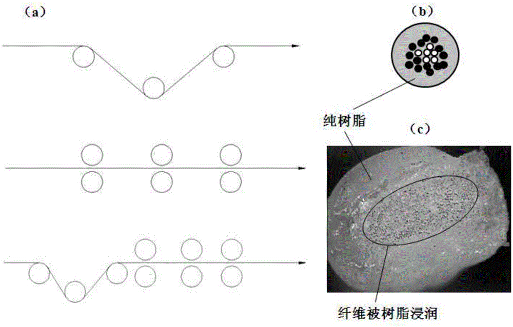

Image

  • Long fiber bundle melt impregnation system
  • Long fiber bundle melt impregnation system
  • Long fiber bundle melt impregnation system

Examples


Embodiment 1

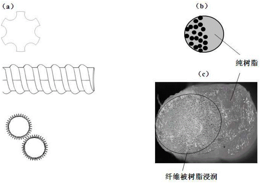
[0071] Such as Image 6 As shown, a long fiber bundle melt impregnation system constructed according to the teachings of the present invention includes a drive unit 31 and an impregnation chamber 32 for providing the rotational power of the drive sleeve roller. The drive unit includes a gear box, a motor, a frequency conversion gears, worm gears, chains, connecting rods and other mechanism components, the impregnation chamber 32 is provided with three sets of matching pairs of drive rollers 33, and the drive rollers 33 are axially provided with arc grooves, the projection of which is The surface graph is a sinusoidal curve with an amplitude of 1 mm and a period of 6. The first driving roller of the matching paired driving sleeve rollers rotates counterclockwise when working, and the second driving roller rotates clockwise. Three sets of matching pairs The rotation mode of the drive sleeve is the same. The side walls of the impregnation chamber 32 are respectively provided wit...

Embodiment 2

[0077] A long fiber bundle melt impregnation system provided by the present invention includes a drive unit and an impregnation chamber for providing rotational power for driving sleeve rollers, and the drive unit includes a gear box, a motor, a frequency converter, a gear, a worm gear, and a chain , connecting rods and other mechanism components, the impregnation chamber is provided with 4 sets of matched pairs of driving sleeve rollers, and the driving sleeve rollers are provided with arc grooves in the axial direction, and the projection surface pattern is 0.5mm in amplitude and 4 Sinusoidal curve, the first driving roller of the matching paired driving sleeve rollers rotates counterclockwise during work, the second driving roller rotates clockwise, and the rotation mode of the 4 sets of matching paired driving sleeve rollers is opposite. The side walls of the impregnation chamber are respectively provided with a long fiber inlet channel, a melt inlet die and an outlet die. ...

Embodiment 3

[0083] A long fiber bundle melt impregnation system provided by the present invention includes a drive unit and an impregnation chamber for providing rotational power for driving sleeve rollers, and the drive unit includes a gear box, a motor, a frequency converter, a gear, a worm gear, and a chain , connecting rods and other institutional components, the impregnation chamber is provided with 5 sets of matched pairs of driving sleeve rollers, and the driving sleeve rollers are provided with arc grooves in the axial direction. curve, the first driving roller of the matching paired driving rollers rotates counterclockwise during work, the second driving roller rotates clockwise, and the rotation mode of the 5 groups of matching paired driving rollers is opposite. The side walls of the impregnation chamber are respectively provided with a long fiber inlet channel, a melt inlet die and an outlet die.

[0084] To produce 50% long glass fiber reinforced TPU (thermoplastic polyuretha...


PUM

PropertyMeasurementUnit
Lengthaaaaaaaaaa
Lengthaaaaaaaaaa

Abstract

The invention provides a long fiber bundle melt impregnation system. The impregnation system includes a driving unit and at least one group of matched and paired driving covered rolls, the driving unit provides power for the driving covered rolls, the driving covered rolls are composed of a first driving roll and a second driving roll, a slit for a long fiber bundle to go through is left between the first driving roll and the second driving roll, the first driving roll and the second driving roll respectively contact with the long fiber bundle in the slit between the rolls when the first driving roll and the second driving roll rotate, and resultant force generated by mutual chimerism of the first driving roll and the second driving roll promotes the long fiber bundle in the slit between the rolls to move. The long fiber bundle melt impregnation system realizes the purposes of reduction of the thickness of the long fiber bundle in the impregnation process and increase of the filament dispersion uniformity of the long fiber bundle, and reaches less fiber breaking loss, full infiltration, uniform dispersion and high-speed stable production in order to obtain a long fiber reinforced thermoplastic plastic with excellent performances.

Description

technical field [0001] The invention relates to the field of forming processing equipment, in particular to a long fiber bundle melting impregnation system. Background technique [0002] Modified plastics is a field of plastics industry involving a wide range of fields, high technological content, and can create huge economic benefits, and plastic modification technology has penetrated into the raw materials and molding processes of almost all plastic products. The development prospect of modified plastics has the following trends: engineering of general plastics, high performance of engineering plastics, low cost of special engineering plastics, application of high technology such as nanocomposite technology, green, environmental protection, low carbon and recycling of modified plastics. use. [0003] Long Fiber Reinforced Thermoplastics (LFT) is a high-performance new material that has made breakthroughs in recent years, which can make up for or replace many shortcomings ...

Claims


Application Information

Patent Timeline
IPC IPC(8): B29B15/14B29B9/06
Inventor 陈剑锐陈光辉徐淑芬
Owner BENSONG ENG PLASTICS HANGZHOU
Learn More