
A two-phase separator

A phase separator and separator technology, which is applied in the field of two-phase separators, can solve the problems of large momentum change, low separation efficiency, turbulent flow field, etc. Effect

Active Publication Date: 2017-04-26
福建伊普思实业有限公司
View PDF5 Cites 0 Cited by
  • Summary
  • Abstract
  • Description
  • Claims
  • Application Information

AI Technical Summary

Problems solved by technology

Since the gas-liquid mixed feed entering the two-phase separator collides with the baffle plate in the initial separation stage, the momentum changes greatly and the flow field is relatively turbulent. The disadvantage of this existing two-phase separator is its separation low efficiency

Method used


Image

  • A two-phase separator
  • A two-phase separator
  • A two-phase separator

Examples


Embodiment Construction

[0026] The present invention will be described in detail below in conjunction with the accompanying drawings and embodiments.

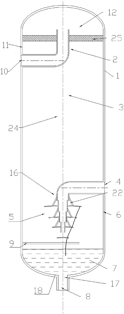
[0027] see figure 1 The two-phase separator of the present invention comprises a generally vertical cylinder body 1, an inlet separation area 16 located at the lower part of the cylinder body, and a liquid accumulation area located at the bottom of the cylinder body are formed in the cylinder body 1 7 and a gas separation zone 3 located above the inlet separation zone 16; the cylinder 1 also has a feed port 4 (position corresponds to an inlet separation zone 16 that the cylinder 1 has, for receiving the gas-liquid mixture) , a gas outlet 10 at the upper end of the cylinder 1 (for gas recovery after separation) and a liquid outlet 8 at the bottom of the cylinder 1 (the position corresponds to a liquid outlet end area 17 that the cylinder 1 has, for liquid collected after separation). The cylinder 1 also includes a primary separator 5 arranged in the ...


PUM

PropertyMeasurementUnit
diameteraaaaaaaaaa
diameteraaaaaaaaaa

Abstract

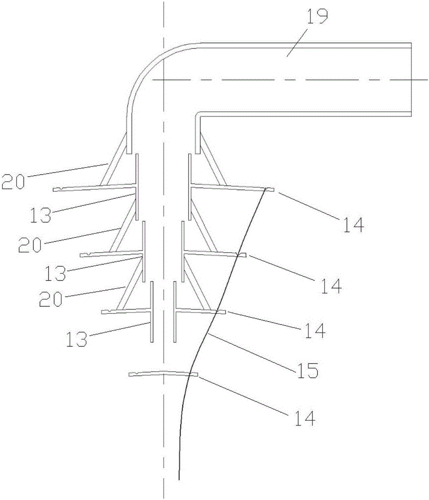
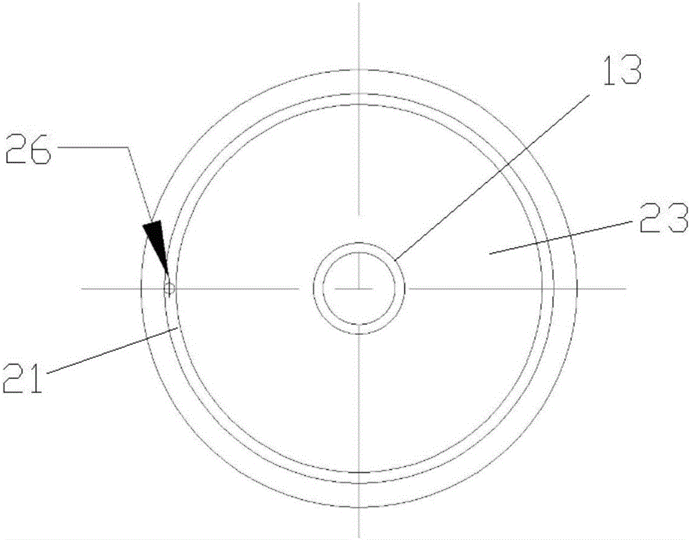
The invention provides a two-phase separator which comprises a barrel and a feed port, a gas outlet and a liquid outlet which are formed in the barrel. A primary separator body is arranged in the barrel and comprises an inlet pipe and multiple layers of casing pipes which are closely arranged from top to bottom end face to end face, the side wall of each layer of the casing pipe is circumferentially provided with a downwards-inclined annular baffle, a disc-shaped baffle which is inclined downwards from the center is arranged under the bottommost-layer casing pipe, and liquid storage grooves formed in the baffles of all the layers are connected through flexible liquid guiding pipes. According to the two-phase separator, by arranging the primary separator body comprising multiple stages of the casing pipes and the baffles at the inlet area of the barrel, a gas-liquid mixture entering the barrel is subjected to multiple times of collision separation, separated liquid is guided into a liquid collection area in time through the flexible liquid guiding pipes to prevent inlet high-speed gas flow from generating impact on subsequent gravity separation, the structure is compact and reliable, and the gas-liquid separation efficiency is improved.

Description

technical field [0001] The invention relates to a two-phase separator, in particular to a gas-liquid two-phase separator. Background technique [0002] Existing two-phase separators include a generally vertical separator cylinder, which usually has an inlet and two outlets, one of which is located in the gas separation area at the top of the separator cylinder, and the other outlet is located at the top of the separator cylinder. In the liquid collecting area at the bottom of the separator cylinder, an inlet baffle is provided in the inlet area of ​​the separator cylinder. [0003] In the actual working process, the mixed gas containing gas and liquid enters the separator cylinder through the inlet, hits the inlet baffle, the momentum changes drastically, and the gas and liquid are initially separated. After the initial separation, the gas moves up into the gravity separation zone and the liquid down into the liquid accumulation zone. Gas and liquid exit the separator barr...

Claims


Application Information

Patent Timeline
Patent Type & Authority Patents(China)
IPC IPC(8): B01D45/08B01D45/02B01D50/00
CPCB01D45/02B01D45/08B01D50/00
Inventor 冯健美刘碧媛王玲子彭学院
Owner 福建伊普思实业有限公司
Learn More