
Method for forming external electrode of electronic component

A technology of electronic components and external electrodes, which is applied in the field of forming external electrodes of electronic components, and can solve problems such as insufficient leveling of conductive paste, traces of end-face electrode grids, and uneven surface of end-face electrodes.

Inactive Publication Date: 2016-04-27
MURATA MFG CO LTD
View PDF9 Cites 2 Cited by
  • Summary
  • Abstract
  • Description
  • Claims
  • Application Information

AI Technical Summary

Problems solved by technology

[0008] In the conventional method for forming end-face electrodes disclosed in Patent Document 1, grid traces are generated on the end-face electrodes, or voids are generated in mesh-embedded parts, and insufficient leveling of the conductive paste occurs. So that it is easy to produce unevenness on the surface of the end electrode

Method used


Image

  • Method for forming external electrode of electronic component
  • Method for forming external electrode of electronic component
  • Method for forming external electrode of electronic component

Examples


Embodiment Construction

[0030] Hereinafter, embodiments of the present invention will be described in detail with reference to the drawings. In addition, in this embodiment, the case where the on-contact printing (on-contact printing) in which a metal mask is brought into contact with an object to be printed and printed is performed when forming an external electrode is demonstrated. However, it is also applicable to non-contact printing (off-contact printing) in which printing is performed without being in contact with a metal mask.

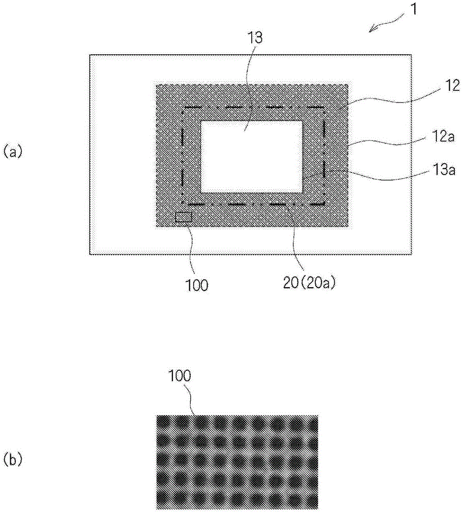
[0031] figure 1 It is a schematic diagram which shows the structure of the metal mask used for the external electrode formation method of the electronic component which concerns on embodiment of this invention. figure 1 (a) shows the top view of the metal mask 1 which concerns on this embodiment, figure 1 (b) shows figure 1 Partial enlarged view of area 100 in (a). In addition, electronic components manufactured by the external electrode forming method of electroni...


PUM


Abstract

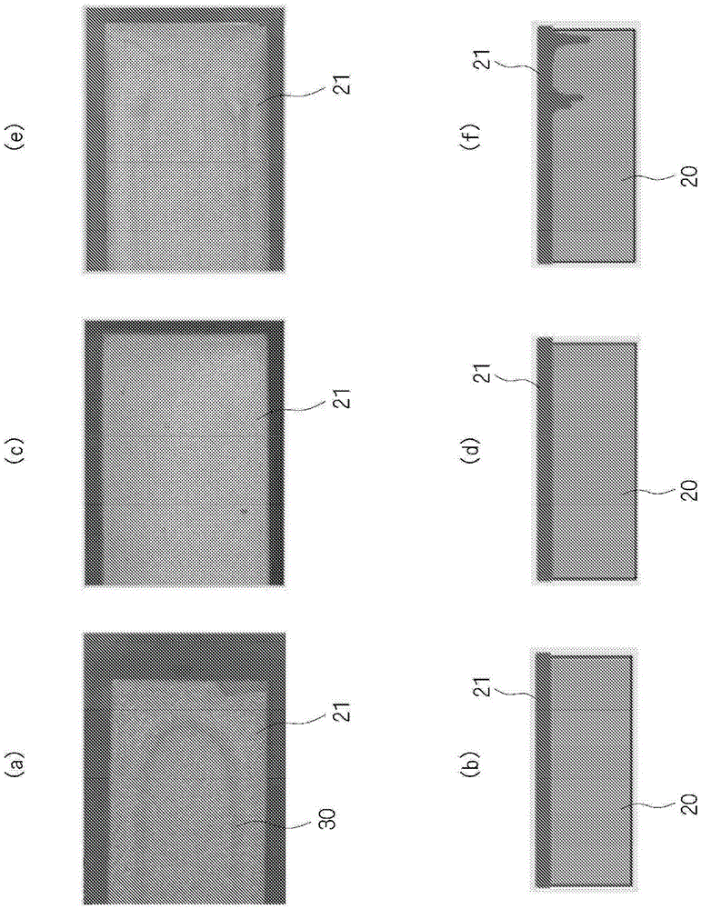
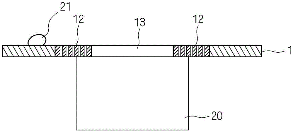
This invention provides a method for forming an external electrode of an electronic component. Said method, whereby a sufficient amount of a conductive paste can be applied all the way to edges, makes it possible to increase the reliability of the electronic component. In said method, a conductive paste (21) is printed onto a printing target (20) via a metal mask (1) comprising a hole (13) and a mesh section (12) that is laid out so as to surround said hole (13). The outer edge of the hole (13) in the metal mask (1) is located inside a printing region on the printing target (20), and the outer edge of the mesh section (12) is located outside said printing region.

Description

technical field [0001] The present invention relates to a method for forming an external electrode of an electronic component capable of reliably covering the end with a conductive paste. Background technique [0002] Conventionally, external electrodes are formed in the manufacturing process of electronic components using a plurality of laminated chips composed of a laminate of a plurality of ceramic layers and a plurality of internal electrode layers. In this case, a screen mask is used to A conductive paste is printed so as to cover the exposed surface of the internal electrode layer. [0003] Patent Document 1 discloses a method for forming end-face electrodes of a surface-mounted electronic component in which electrodes are embedded in the mesh portion and photoresist portion of the opening of the screen mask. Material paste (conductive paste), after scraping off excess conductive paste, use the platform for end-face electrodes to print end-face electrodes. [0004] p...

Claims


Application Information

Patent Timeline
IPC IPC(8): H01G4/30H01G13/00H01G4/232
CPCB41N1/24H01G4/2325H01G4/30H01G13/006H01F41/32H03H3/007
Inventor 北村俊辅胜部彰夫
Owner MURATA MFG CO LTD
Learn More