
Digital FM receiver threshold expansion system and method

A threshold extension, digital frequency modulation technology, applied in transmission systems, electrical components, etc., can solve the problems of low sensitivity, poor effect, weakening jumps, etc., and achieve the effect of improving the signal-to-noise ratio.

Active Publication Date: 2016-04-27
APPOTECH
View PDF7 Cites 0 Cited by
  • Summary
  • Abstract
  • Description
  • Claims
  • Application Information

AI Technical Summary

Problems solved by technology

[0007] 1. Reduce the modulation degree and narrow the signal bandwidth, so that a narrower RFBPF can be used to filter out more carrier noise, thereby improving the signal-to-noise ratio of the demodulated signal, such as FMFB; but due to the reduced modulation degree, the not good
[0008] 2. As mentioned in the Chinese invention patent application with the publication number CN1115833, by detecting and removing the phase jump of the demodulated signal, thereby improving the signal-to-noise ratio of the demodulated signal; but this method can only detect a part of the jump, and Even if a jump is detected, it can only weaken the jump and cannot accurately restore the correct signal. The signal-to-noise ratio of the demodulated signal has limited improvement
[0009] 3. As mentioned in the Chinese invention patent application with the publication number CN101420239, the RFBPF with variable bandwidth and variable attenuation slope is used to adapt to different carrier signal-to-noise ratios, and to filter out more carrier noise without causing sound distortion , so as to improve the signal-to-noise ratio of the demodulated signal; but because the sound is not distorted, the bandwidth of the RFBPF is reduced while the attenuation slope of the RFBPF is also slower, so the final increase in sensitivity is not great

Method used


Image

  • Digital FM receiver threshold expansion system and method
  • Digital FM receiver threshold expansion system and method
  • Digital FM receiver threshold expansion system and method

Examples


Embodiment Construction

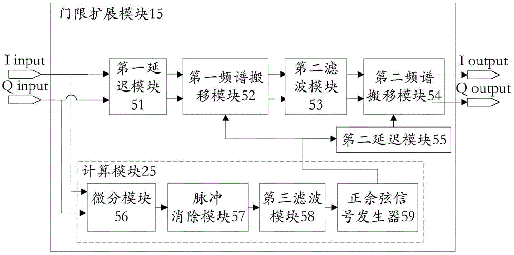
[0030] see figure 2 , figure 2 It is a structural block diagram of an embodiment of the threshold extension system of the digital FM receiver of the present invention. The threshold extension system of the present invention includes an analog front-end module 11 , an analog-to-digital conversion module 12 , a frequency mixing module 13 , a first filter module 14 , a threshold extension module 15 and a demodulation module 16 .

[0031]The analog front-end module 11 is used to receive the FM signal and converts the carrier frequency of the received FM signal to an intermediate frequency to generate an intermediate frequency signal; the analog-to-digital conversion module 12 is used to perform analog-to-digital conversion on the intermediate frequency signal to obtain a digital signal; the frequency mixing module 13, That is, the complex mixer is used to mix the digital signal to direct current to obtain the mixed frequency signal; the first filter module 14, namely the FIRLPF...


PUM


Abstract

The invention provides a digital FM receiver threshold expansion system and a method. The digital FM receiver threshold expansion system comprises a simulation front end module, a frequency mixing module, a first filtering module, a threshold expansion module and a demodulation module. The threshold expansion module comprises a first delay module and delays a first filtering signal to obtain a first delay signal; a first frequency spectrum conveying module performs the spectrum conveying on the first delay signal to obtain a first conveying signal; a second filtering module performs filtering on the first conveying signal; a second spectrum conveying module conveys the filtered first conveying signal to the initial position to obtain a threshold expansion signal; the calculation module receives a first filtering signal and calculates a calculation signal according to the first filtering signal; and the calculation module outputs the calculation signal to the first spectrum conveying module and the second delay module. The method is applied to the digital FM receiver threshold expansion system. The invention filters the multicarrier noise, improves the signal to noise ratio of the demodulation signal and prevents the distortion of the sound.

Description

technical field [0001] The invention belongs to the field of digital frequency modulation, in particular to a method and equipment for digitally demodulating frequency modulation signals such as stereo broadcast signals, in particular to a threshold expansion system and method for digital frequency modulation (FM) receivers. Background technique [0002] The purpose of an FM receiver is to base the received radio signal on to restore the modulated signal . The frequency modulated carrier signal is expressed as [0003] [0004] in Is the carrier frequency; D is the frequency modulation degree, generally 75KHz; is the modulated signal. [0005] The structural block diagram of the current common digital FM receiver is as follows: figure 1 As shown, the analog front-end module 1 converts the RF (Radio Frequency: radio frequency) of the received FM signal to an intermediate frequency (Intermediate Frequency: intermediate frequency) and filters it to obtain two IQ si...

Claims


Application Information

Patent Timeline
Patent Type & Authority Applications(China)
IPC IPC(8): H04B1/10
CPCH04B1/10H04B1/1036H04B2001/1054
Inventor 陈文捷
Owner APPOTECH
Learn More