V-type regulating ball valve
- Summary
- Abstract
- Description
- Claims
- Application Information
AI Technical Summary
Problems solved by technology
Method used
Image
Examples
Embodiment Construction
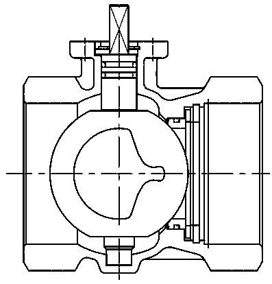
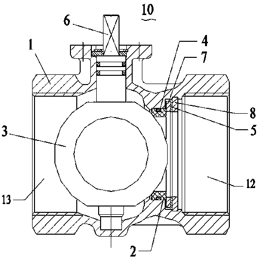
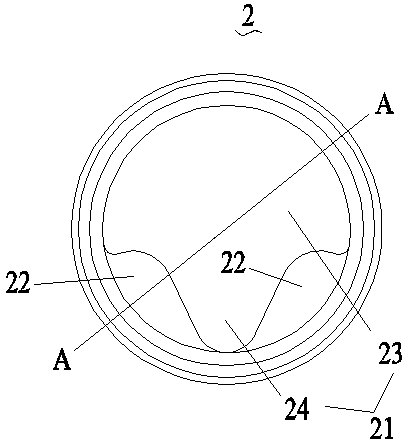
[0030] The present invention is further described below in conjunction with accompanying drawing, refer to figure 2 The V-shaped regulating ball valve 10 includes a valve body 1, a valve seat 2, a ball core 3, a seal 4, an axial displacement compensator 5, a valve stem 6, a pressure plate 7 and a snap ring 8, and the valve body 1 has a straight flow channel 11, One end of the direct-flow channel 11 is a fluid inlet 12, and the other end of the direct-flow channel 11 is a fluid outlet 13, and an external thread or an internal thread is set at the fluid inlet 12 and the fluid outlet 13; Figure 2 to Figure 4 , the valve seat 2 is an annular structure, the valve seat 2 is provided with an inner hole 21, and a raised portion 22 is extended on the inside of the valve seat 2 close to the assembled ball core 3, so that the inner hole 21 of the valve seat 2 forms a flow control valve. characteristics, and the contact surface between the raised portion 22 and the ball core 3 is an arc...
PUM
 Abstract
Description
Claims
Application Information
 - R&D
- Intellectual Property
- Life Sciences
- Materials
- Tech Scout
- Unparalleled Data Quality
- Higher Quality Content
- 60% Fewer Hallucinations
Browse by: Latest US Patents, China's latest patents, Technical Efficacy Thesaurus, Application Domain, Technology Topic, Popular Technical Reports.
© 2025 PatSnap. All rights reserved.Legal|Privacy policy|Modern Slavery Act Transparency Statement|Sitemap|About US| Contact US: help@patsnap.com


