SCR (selective catalytic reduction) denitration device for low-dust flue gas in thermal power plant and denitration method

A technology for thermal power plants and SCR reactors, applied in the field of exhaust gas purification, can solve the problems of high dust concentration in flue gas, wear and tear of SCR flue and equipment, and inability to use it, so as to improve operating economy, reduce project investment, and save transformation. effect of work

Active Publication Date: 2016-04-27
BEIJING LONGYUAN ENVIRONMENTAL ENG CO LTD
View PDF3 Cites 9 Cited by
  • Summary
  • Abstract
  • Description
  • Claims
  • Application Information

AI Technical Summary

Problems solved by technology

In order to meet the appropriate reaction temperature of the SCR catalyst, the SCR reactor is currently installed between the outlet of the boiler economizer and the inlet of the air preheater. The dust concentration of the gas is very high, generally 20-50g / m 3 In between, the wear of the SCR flue and equipment is also very serious
[0003] In addition, for some established units (especially old units) that have no denitrification space reserved between the economizer and the air preheater, how to carry out SCR denitrification is a topic worth studying when higher denitrification efficiency is required. If the denitrification equipment (SCR reactor) is arranged after the dust collector, although it can flexibly solve the problem of the space occupied by the denitrification facility, it also has the problem that the flue gas temperature cannot meet the high-efficiency catalytic reaction temperature range of the high-temperature catalyst, and the target denitrification cannot be achieved efficiency, for the following reasons:
[0004] (1) The flue gas after the dust collector has been cooled by the boiler air preheater, and the temperature range of the flue gas is generally between 110°C and 180°C, which is far lower than the normal catalytic reaction temperature range of the high-temperature catalyst, so mature, Inexpensive and reliable high-temperature catalysts to improve denitrification efficiency;
[0005] (2) The so-called low-temperature catalyst (catalytic reaction temperature below 200°C) is used to meet the lower flue gas reaction temperature requirements. Due to the low reaction temperature and relatively low catalyst activity, the volume of the catalyst must be increased to ensure high denitrification efficiency , NO at the entrance X Under the design conditions of the same concentration, the volume of the low-temperature catalyst will increase to 2 to 3 times that of the high-temperature catalyst, which will lead to a substantial increase in equipment volume and catalyst cost.
In addition, when the flue gas temperature is lower than 200 °C, the excess NH in the flue gas 3 (injection required for denitrification) and SO 3 The reaction produces ammonium salts such as ammonium bisulfate. The deposition of ammonium salts is easy to block and corrode the catalyst and equipment, which brings great safety hazards to the operation of the system.

Method used


Image

  • SCR (selective catalytic reduction) denitration device for low-dust flue gas in thermal power plant and denitration method
  • SCR (selective catalytic reduction) denitration device for low-dust flue gas in thermal power plant and denitration method
  • SCR (selective catalytic reduction) denitration device for low-dust flue gas in thermal power plant and denitration method

Examples


Embodiment Construction

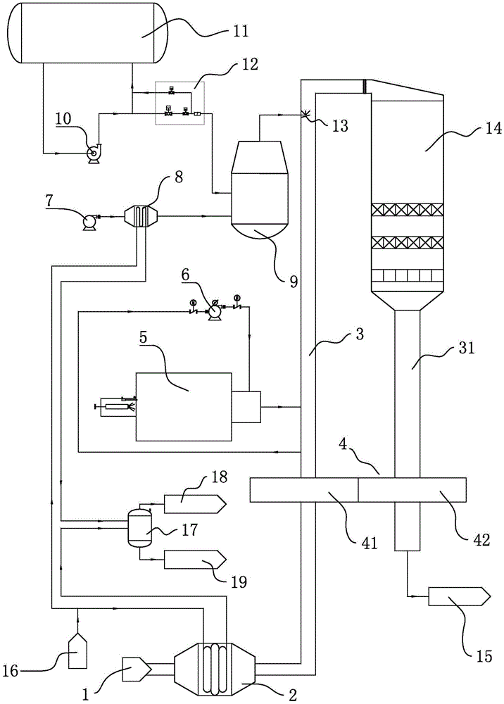
[0035] like figure 1 As shown, the flue includes the original flue gas flue 3 and the clean flue gas flue 31. The inlet end of the original flue gas flue 3 is provided with a flue gas steam heater 2, and the flue gas 1 after the dust collector of the unit passes through the inlet end. Into the flue gas steam heater 2. The outlet end of the original flue gas flue 3 is provided with an SCR reactor 14, the SCR reactor 14 communicates with the clean flue gas flue 31, and the flue gas treated by the SCR reactor 14 is discharged through the clean flue gas flue 31, where it can be It is connected with the discharge interface 15 set by the user according to actual needs. The denitrification device of the present application also includes a flue gas heat exchanger 4 which is internally divided into an original flue gas chamber 41 and a clean flue gas chamber 42. The flue gas flue 31 is connected. The original flue gas flue 3 communicates with the hot blast stove 5 . For the conveni...


PUM


Abstract

The invention provides an SCR (selective catalytic reduction) denitration device for low-dust flue gas in a thermal power plant and a denitration method and relates to a device and a method for purifying exhaust gas by adopting a reactant injection catalytic method. The SCR denitration device for the low-dust flue gas in the thermal power plant comprises a flue gas steam heater, an air steam heater, a steam drainage system, a hot blast heater, an SCR reactor, a flue gas heat exchanger, an ammonia water storage and supply system, an ammonia water evaporator and related auxiliary equipment. According to the denitration method, boiler flue gas from the rear part of a dust remover is treated by the device, the flue gas is heated by combining the high-temperature hot blast heater, the flue gas steam heater and the rotary flue gas heat exchanger, and accordingly, the purposes of energy saving, consumption reduction and operating cost reduction are achieved.

Description

technical field [0001] The present invention relates to a general method for purifying exhaust gas and equipment or devices specially designed for this type of method, in particular to a device and method for purifying exhaust gas by using a catalytic method of injecting reactants. Background technique [0002] Among many flue gas denitrification technologies, selective catalytic reduction (SCR) technology is currently the most widely used technology for flue gas denitrification in large thermal power plants. The denitrification efficiency of SCR flue gas denitrification technology can reach more than 90%, which is the most mature and reliable denitrification technology. The principle is that under the action of the catalyst, the reducing agent NH 3 Preferential and selective NO in flue gas X reaction, the NO in the flue gas X Reduction to nitrogen and water, the effective reaction temperature range of the catalyst must be between 300°C and 400°C. In order to meet the ap...

Claims


Application Information

Patent Timeline
Patent Type & Authority Applications(China)
IPC IPC(8): B01D53/86B01D53/56
CPCB01D53/565B01D53/8628B01D2251/2062B01D2258/0283
Inventor 王小立何强石京科周陵生薛军
Owner BEIJING LONGYUAN ENVIRONMENTAL ENG CO LTD
Why Eureka
Try Eureka