
Transformer

A transformer and capacitor technology, applied in the field of transformers, can solve the problems of inductive reactive power compensation in long-distance power transmission systems, limited transformer capacity, high loss, etc., and achieve the effect of large inductive reactive power compensation, increase excitation current, and reduce total loss

Inactive Publication Date: 2016-04-20
YUNNAN POWER GRID CO LTD ELECTRIC POWER RES INST
View PDF7 Cites 4 Cited by
  • Summary
  • Abstract
  • Description
  • Claims
  • Application Information

AI Technical Summary

Problems solved by technology

[0005] The embodiment of the present invention provides a transformer to solve the problems caused by the coil resistance of the conventional iron core transformer in the prior art and the AC hysteresis loss and core saturation that occur on the iron core during the working process. The problem of limited transformer capacity, high loss and inability to provide inductive reactive power compensation for long-distance power transmission systems

Method used


Image

  • Transformer
  • Transformer

Examples


Embodiment 1

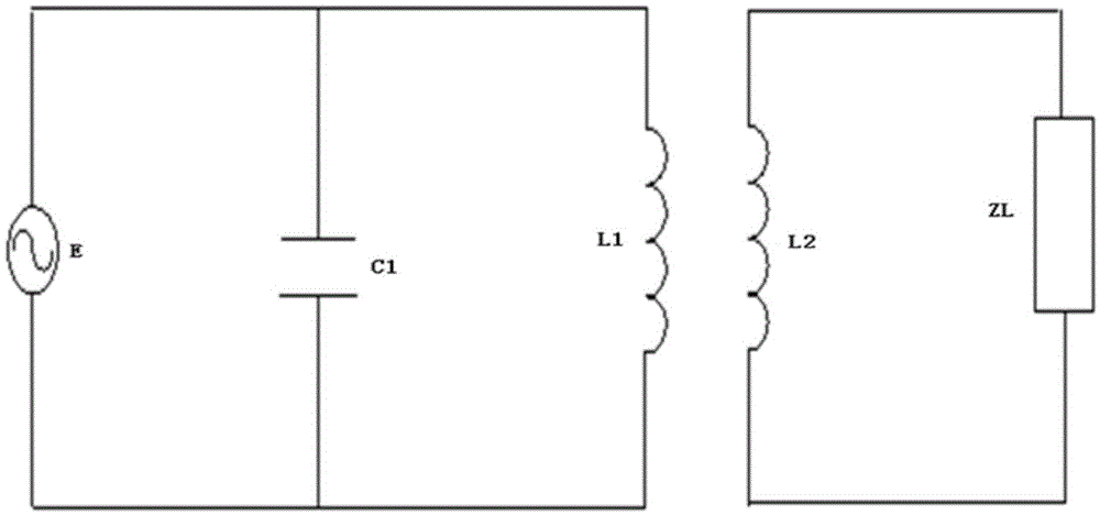
[0021] see figure 1 , which is a schematic circuit diagram of a transformer provided by an embodiment of the present invention. The transformer disclosed in this embodiment includes a primary coil L1 and a secondary coil L2, the primary coil L1 is electrically connected to the power supply E, and the secondary coil L2 is electrically connected to the load ZL, wherein the primary coil L1 and the secondary coil L2 are hollow structure, that is, the coreless structure, and the primary coil L1 and the secondary coil L2 are both superconducting coils, which are used to reduce the total loss on the transformer and overcome the AC hysteresis loss and the The problem of limiting the transmission capacity of the transformer caused by core saturation, and by making full use of the magnetic flux leakage, the transformer can provide a certain amount of inductive reactive power compensation to the system. In addition, a controllable capacitor C1 is provided between the primary coil L1 and...

Embodiment 2

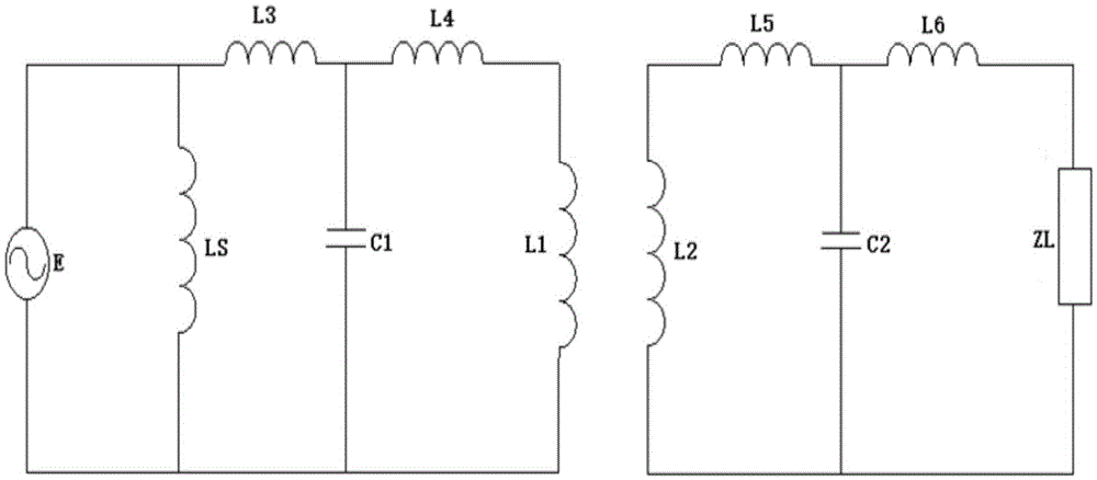
[0023] see figure 2 , is a schematic circuit diagram of another transformer provided by the embodiment of the present invention. For the transformer disclosed in this embodiment, in order to better provide suitable inductive reactive power compensation for the system, a reactor LS is also arranged between the primary coil L1 and the power supply E, and the reactor LS is connected in parallel with the primary coil L1, or A capacitor C2 is also provided between the secondary coil L2 and the load ZL, which is connected in parallel with the secondary coil L2, or between the reactor LS and the controllable capacitor C1 and between the controllable capacitor C1 and the primary coil L1 A first reactor L3 and a second reactor L4 adapted to the controllable capacitor C1 are also provided, and the first reactor L3 and the second reactor L4 may be reactors with the same reactance, such as the capacitance of the controllable capacitor C1 When it is 8uF, the reactance value of the corres...


PUM


Abstract

An embodiment of the invention discloses a transformer, comprising a primary coil and a secondary coil. The primary coil is electrically connected with a power supply, and the secondary coil is electrically connected with a load, wherein a hollow structure is provided between the primary coil and the secondary coil, the primary coil and the secondary coil are superconducting coils, a controllable capacitor is disposed between the primary coil and the power supply, and the controllable capacitor and the primary coil are connected in parallel. Compared with the prior art, the transformer provided by the embodiment of the invention has no core structure; on one hand, exciting current is greatly increased, and high sensitive reactive power compensation can be provided for a system as leakage reactance increases; the other hand, the saturation problem of a core is basically solved, transformer capacity is improved, and the setting of the superconducting coils reduces total loss of the transformer and improves transformer efficiency on the whole.

Description

technical field [0001] The invention relates to the field of electric equipment, in particular to a transformer. Background technique [0002] Modern power transformer is a kind of power equipment with high reliability and high efficiency. With the rapid development of my country's electric power industry and urban construction, the transformer industry has developed rapidly accordingly. [0003] In the prior art, a normally conductive iron core transformer generally consists of a primary coil, a secondary coil and an iron core. The transformer uses the electromagnetic induction between the primary coil and the secondary coil to increase or decrease the voltage, and then realize the purpose of transferring electric energy from one circuit to another. The existence of the resistance of the primary and secondary coils in the normally conductive iron core transformer causes the loss of electric energy on the transformer, especially for the high voltage long-distance transmiss...

Claims


Application Information

Patent Timeline
Patent Type & Authority Applications(China)
IPC IPC(8): H01F36/00H01F27/30H01F27/40
CPCH01F27/306H01F27/40H01F36/00Y02E40/60
Inventor 黑颖顿胡南南马宏明王科宋萌
Owner YUNNAN POWER GRID CO LTD ELECTRIC POWER RES INST
Learn More