
Two-way time reversal damage imaging method based on ultrasonic guided-wave

An ultrasonic guided wave and two-way time technology, which is applied in the analysis of solids using sound waves/ultrasonic waves/infrasonic waves, material analysis using sound waves/ultrasonic waves/infrasonic waves, and measuring devices. It can solve small path differences, different paths, and short paths. problem, to achieve the effect of enhancing signal amplitude, improving signal-to-noise ratio, improving resolution and accuracy

Active Publication Date: 2016-04-20
SOUTH CHINA UNIV OF TECH +1
View PDF5 Cites 21 Cited by
  • Summary
  • Abstract
  • Description
  • Claims
  • Application Information

AI Technical Summary

Problems solved by technology

[0005] However, the traditional time reversal method requires that the path of the signal from the damage to the receiving array unit is short and different, and the required number of receiving array units is as large as possible to compensate for the propagation loss, so that the damage target point may become a spatial The point where the maximum signal is located is detected
For the slender solid structure, the guided wave is mostly propagated by plane wave, and the path difference between the radial elements on the same side is small, so it is difficult to realize the traditional time inversion method.

Method used


Image

  • Two-way time reversal damage imaging method based on ultrasonic guided-wave
  • Two-way time reversal damage imaging method based on ultrasonic guided-wave
  • Two-way time reversal damage imaging method based on ultrasonic guided-wave

Examples


Embodiment Construction

[0026] In order to make the object, technical solution and advantages of the present invention clearer, the present invention will be further described in detail below in conjunction with the embodiments and accompanying drawings.

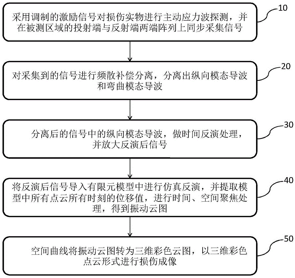
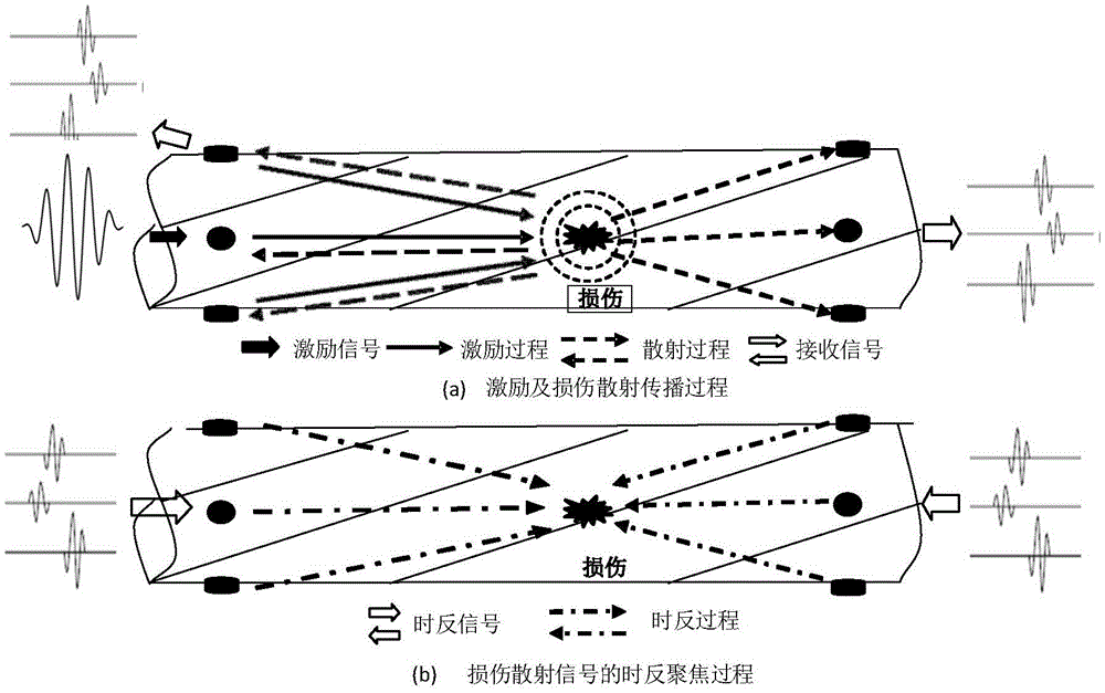
[0027] Such as figure 1 As shown in , the two-way time-reversal damage detection method based on ultrasonic guided waves is shown, and the method is illustrated by selecting a slender detection model case (such as figure 2 shown in a and b):

[0028] Step 10: Use the modulated excitation signal to perform active stress wave detection on the damaged object, and collect signals synchronously on the arrays at both ends of the projection end and reflection end of the measured area;

[0029] Load the initial excitation signal on the excitation transducer array: the initial excitation signal is a 5-peak sinusoidal narrowband signal modulated by a Hanning window. In the implementation case, 75Khz is selected, the amplitude is 3Vpp, and the power amplifi...


PUM


Abstract

The invention discloses a two-way time reversal damage imaging method based on ultrasonic guided-wave. The method comprises the following steps: carrying out active stress wave detection on a damaged object by the use of a modulated excitation signal, and synchronously acquiring signals at a transmission end and a reflective end of a detected area; carrying out frequency dispersion compensation separation on the acquired signals, and separating longitudinal mode guided wave and bending mode guided wave; extracting the longitudinal mode guided wave in the separated signals, carrying out time reversal treatment, and amplifying the reversed signal; carrying out simulation reversal by importing the reversed signal into a finite element model, extracting displacement values of all point clouds and moments in the model, and carrying out time and space focusing treatment to obtain a vibration cloud map; and defining a space curve to convert the vibration cloud map into a three-dimensional color map, and carrying out damage imaging by three-dimensional color point cloud. According to the method, characteristics of damages are analyzed from an overall perspective, and different mode guided waves are innovatively extracted to carry out time reversal analysis of transmission and reflective ends simultaneously. The method of the invention has important academic value and practical significance.

Description

technical field [0001] The invention relates to the technical field of non-destructive testing, in particular to a two-way time-reversal damage imaging method based on ultrasonic guided waves for elongated structures. Background technique [0002] In various fields such as transportation, building bridges, and power transmission cables, various complex long-shaped structures such as twisted wires, pipes, and steel wire ropes are often used. These complex structures will be affected by the external environment for a long time during work. Various damages, such as wear, corrosion, broken strands, etc., these damages cause great hidden dangers and threaten the safety of personnel, equipment and property. Therefore, the detection of such complex elongated structures is of great significance, and many detection methods have emerged. [0003] At present, according to whether stress wave is used for damage detection, it can be divided into two categories: non-stress wave damage de...

Claims


Application Information

Patent Timeline
Patent Type & Authority Applications(China)
IPC IPC(8): G01N29/06
CPCG01N29/069
Inventor 洪晓斌周建熹
Owner SOUTH CHINA UNIV OF TECH
Learn More