
Field Measurement Method of Surface Reflectance Coefficient

A ground reflection coefficient and on-site measurement technology, which is applied in the direction of measuring devices, material analysis using radiation diffraction, material analysis using wave/particle radiation, etc., can solve the problems of large coefficient errors, etc., and achieve small errors, simple configuration, and operation easy effect

Inactive Publication Date: 2018-05-15
BEIJING INSTITUTE OF TECHNOLOGYGY
View PDF3 Cites 2 Cited by
  • Summary
  • Abstract
  • Description
  • Claims
  • Application Information

AI Technical Summary

Problems solved by technology

[0005] The purpose of the present invention is to provide an on-site measurement method of ground reflection coefficient in order to solve the problem of large coefficient errors in the prior art

Method used


Image

  • Field Measurement Method of Surface Reflectance Coefficient
  • Field Measurement Method of Surface Reflectance Coefficient
  • Field Measurement Method of Surface Reflectance Coefficient

Examples


Embodiment 1

[0047] The on-site measurement method of the ground reflection coefficient, the specific steps are as follows:

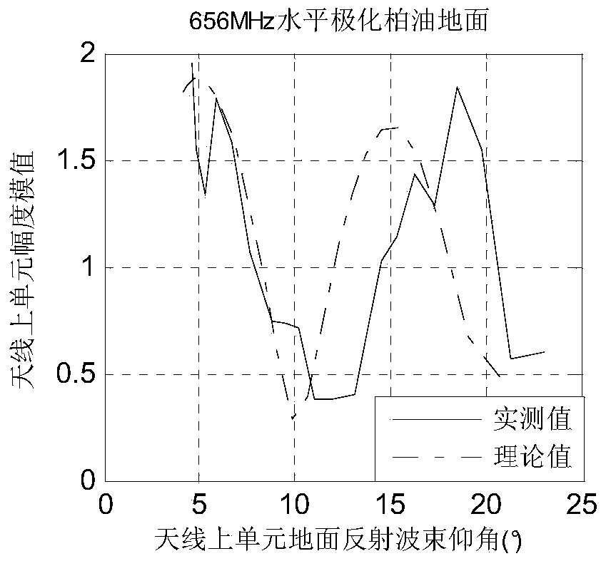
[0048] Step 1. Both the test antenna and the receiving antenna are horizontally polarized, and placed in the middle of the asphalt road. The specific configuration diagram is as follows figure 2 As shown, the height of the phase center of the lower unit of the receiving antenna from the ground is 1.95m, the height of the phase center of the upper unit of the receiving antenna is 2.47m from the ground, and the height of the phase center of the test antenna unit from the ground is 2.21m. Connect the test antenna to the signal source and set The signal source frequency is 656MHz, the transmission power is 0dB, and the receiving channel correction is performed at a distance of 2m from the test antenna to the receiving antenna;

[0049] Step 2. Record step 1. Test the antenna signal source power 0dB, record the signal amplitude values ​​of the two antenna units, and rec...


PUM


Abstract

The invention relates to a field measuring method for ground reflection coefficients and belongs to the field of radar signal processing. Under the influence of ground reflection, a pitching directional diagram of a radar antenna is subjected to serious beam split, so that the measurement for the detection and elevation of the target is further influenced. In order to more accurately acquire the ground reflection coefficients under different ground conditions, the invention provides the field measuring method for ground reflection coefficients. The method comprises the following steps: (1) correcting a channel and acquiring all the parameters required by normalization; (2) performing stepping measurement: recording an amplitude ratio of upper and lower antenna elements at each time; (3) calculating an estimated value rho' of the ground reflection coefficients; (4) setting a diffusion factor D and a ground surface altitude standard deviation sigma h according to the practical conditions and calculating the estimated value of a ground complex dielectric constant epsilon r; (5) selecting the epsilon r with minimum error. According to the method, the ground reflection coefficients of different ground surfaces can be more effectively calculated and the pitching directional diagram of antenna can be more accurately drawn.

Description

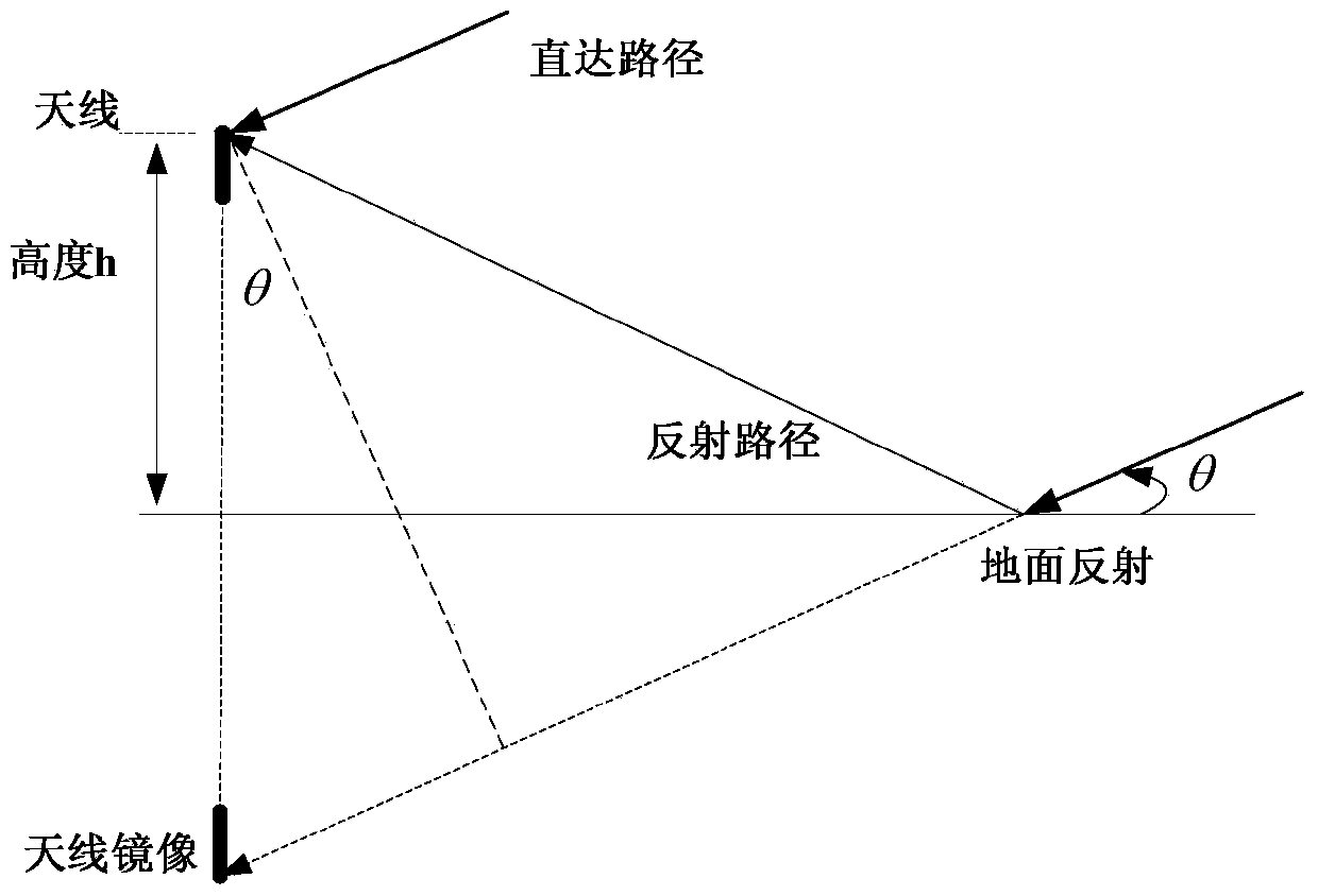
technical field [0001] The invention relates to an on-site measurement method of ground reflection coefficient, which is used for estimating antenna elevation pattern and belongs to the field of radar signal processing. Background technique [0002] In addition to the direct signal reflected by the target, the echo signal received by the radar antenna also has the signal reflected by the ground and reaches the receiving antenna, as shown in the attached figure 1 As shown, due to the influence of ground reflection, serious beam splitting will occur in the elevation pattern, which will affect the detection of targets and the measurement of elevation angles. Compared with free space, the detection power of targets at different elevation angles will have a large deviation. The measurement will also be affected. If it can be effectively measured, not only can the system performance be better estimated, but also the source of the error can be analyzed and avoidance measures can be...

Claims


Application Information

Patent Timeline
Patent Type & Authority Patents(China)
IPC IPC(8): G01N23/20
CPCG01N23/20G01N2223/052G01N2223/614G01N2223/616
Inventor 单涛冯远陶然孙浩洋
Owner BEIJING INSTITUTE OF TECHNOLOGYGY
Learn More