
An aerosol sampling and dehumidification method and device

An aerosol and airflow technology, applied in the field of dehumidification, can solve the problems of monitoring system safety without more consideration, affecting the share of collection, changing chemistry, etc., to overcome the serious problem of aerosol loss, guarantee lifespan, and simple operation.

Active Publication Date: 2020-07-03
CHINA INST FOR RADIATION PROTECTION
View PDF4 Cites 0 Cited by
  • Summary
  • Abstract
  • Description
  • Claims
  • Application Information

AI Technical Summary

Problems solved by technology

[0004] (2) Even if the radioactive aerosol sampling technique complies with the specifications, there is no more consideration when encountering moisture and condensation that may affect the accuracy of sampling and the safety of the monitoring system
[0005] (3) A small number of devices that consider and set up dehumidification also think that dehumidification can be achieved as long as they are connected. Even if dehumidification is possible, there may be cases where condensed water or liquid substances exist before the sampling terminal, which will affect sampling and measurement or even damage the measurement system.
[0006] (4) The heating treatment method is adopted in foreign PM2.5 monitoring, which can reduce the humidity condensation problem, but it cannot completely solve it, and the heating method will affect the share of subsequent collection, change the chemistry and change the performance of the detection system, etc. many disadvantages

Method used


Image

  • An aerosol sampling and dehumidification method and device
  • An aerosol sampling and dehumidification method and device

Examples


Embodiment Construction

[0032] The specific implementation manners of the present invention will be further described in detail below in conjunction with the accompanying drawings.

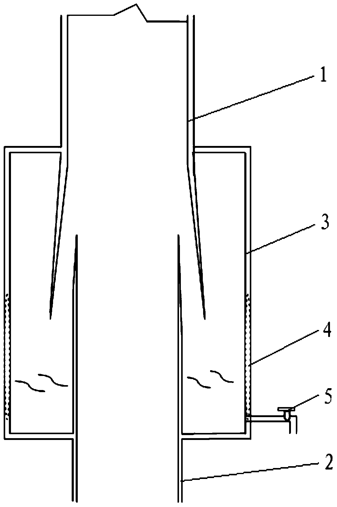
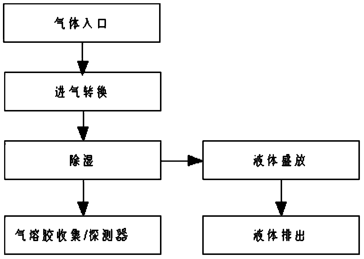
[0033] like figure 1 Shown is the aerosol sampling and dehumidification device provided by the present invention. The dehumidification device is not only suitable for dehumidification of radioactive aerosol sampling, but also suitable for dehumidification of non-radioactive aerosol or PM sampling. The dehumidification device is arranged on the gas transmission pipeline at the front end of the sampling or detection system, which includes an upper elbow 1 , a lower elbow 2 and a liquid container 3 . Wherein, the lower bend pipe 2 is arranged below the upper bend pipe 1, preferably directly below the upper bend pipe. The opening angle of the splayed structure of the elbow, the lower part of the upper elbow is sleeved on the upper part of the lower elbow, and there is a gap in the sleeve part; the lower part of the upper el...


PUM


Abstract

The present invention relates to an aerosol sampling and dehumidifying apparatus and an aerosol sampling and dehumidifying method. According to the present invention, the apparatus is arranged on a gas transmission pipeline on the front end of a sampling or detecting system, and comprises an upper bending pipe, a lower bending pipe and a liquid state holding container, wherein the lower bending pipe is arranged below the upper bending pipe, the lower portion of the upper bending pipe and the upper portion of the lower bending pipe respectively have an inverted V-shaped structure, the lower portion of the upper bending pipe is sleeved on the upper portion of the lower bending pipe, the gap is arranged between the lower portion of the upper bending pipe and the upper portion of the lower bending pipe, and the lower portion of the upper bending pipe and the upper portion of the lower bending pipe are respectively arranged inside the liquid stage holding container in a penetrating manner; with the dehumidifying apparatus, the condensed liquid substance of the aerosol entering the upper bending pipe from the gas transmission pipeline is attached onto the pipe wall of the upper bending pipe to achieve gas-liquid separation, such that the interference of the wet gas on the sampling and the damage of the wet gas on the detecting system during the sampling can be overcome, and the serious aerosol loss problem of the conventional heating and dehumidifying method is overcome so as to maximally protect the sampling system and the detecting system; and the dehumidifying method has characteristics of simple operation and good effect.

Description

technical field [0001] The invention belongs to the technical field of dehumidification, and in particular relates to an aerosol sampling and dehumidification method and device. The device is not only suitable for radioactive aerosol sampling, but also suitable for common aerosol or PM sampling. Background technique [0002] With the impact of the Japanese nuclear power accident and the PM2.5 problem, people have become more and more aware of the hazards of radioactive aerosols and non-radioactive aerosols, and aerosol monitoring technology has made great progress from nuclear energy-related fields to comprehensive industries. However, the aerosol monitoring technology is not a simple one, as long as you can pump air, you can get the aerosols you need to pay attention to. Moreover, sampling and monitoring interact with humidity, temperature, etc., and the relationship is complicated. The current situation can be summarized as follows: [0003] (1) Radioactive aerosol monit...

Claims


Application Information

Patent Timeline
Patent Type & Authority Patents(China)
IPC IPC(8): G01N1/22G01N1/34
Inventor 沈福
Owner CHINA INST FOR RADIATION PROTECTION
Learn More