A kind of pipe outer wall automatic rust removal device and outer wall automatic rust removal method

An automatic technology for the outer wall of a pipeline, applied in cleaning methods and utensils, chemical instruments and methods, cleaning hollow objects, etc., can solve problems such as rust stains, pipeline leakage, etc., to achieve the effect of convenient use, avoid foreign body damage, and easy disassembly

Active Publication Date: 2017-07-18
石家庄德贤建筑工程有限公司
View PDF11 Cites 0 Cited by
  • Summary
  • Abstract
  • Description
  • Claims
  • Application Information

AI Technical Summary

Problems solved by technology

[0002] After long-term use, the pipeline is prone to rust stains due to the corrosion of the external environment. In severe cases, it will cause pipeline leakage and affect its use

Method used


Image

  • A kind of pipe outer wall automatic rust removal device and outer wall automatic rust removal method
  • A kind of pipe outer wall automatic rust removal device and outer wall automatic rust removal method

Examples


Embodiment 1

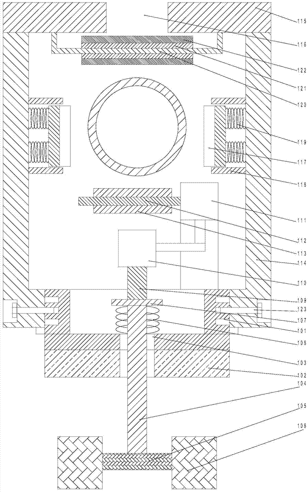
[0022] like figure 1 , 2 As shown, an automatic derusting device for the outer wall of a pipeline includes a bracket 101 and an electromagnet 102 arranged below the bracket 101. Threaded holes arranged at equal intervals are arranged in the height direction of the side walls on both sides of the bracket 101. The two sides of the bracket 101 are respectively provided with a fixing frame 114, and a through hole 1 is respectively arranged on the two described fixing frames 114, and a fastening bolt 123 is arranged in the said through hole 1. The bolts 123 pass through the through holes and are screwed into the threaded holes on the side wall of the support 101. Positioning plates 115 are respectively arranged on the upper ends of the two fixing brackets 114. The two positioning plates 115 are arranged facing each other, and a cavity 116 is provided between the facing end faces of the two positioning plates 115. The width of the cavity 116 is smaller than the diameter of the pipe...

Embodiment 2

[0028] On the basis of Example 1, the present invention also discloses a method for automatic rust removal on the outer wall of a pipeline, which includes the following steps:

[0029] S1: Fix the two positioning plates 115 above the pipe, fix the fixing frame 114 under the positioning plate 115, make the driving gear 113 under the pipe, and move the fixing frame 114 longitudinally, so that the fixing frame 114 is connected by fastening bolts 123 bolts On the side wall of the bracket 101, and adjust the height of the fixed frame 114 by adjusting the position of the threaded hole connected by the fastening bolt 123;

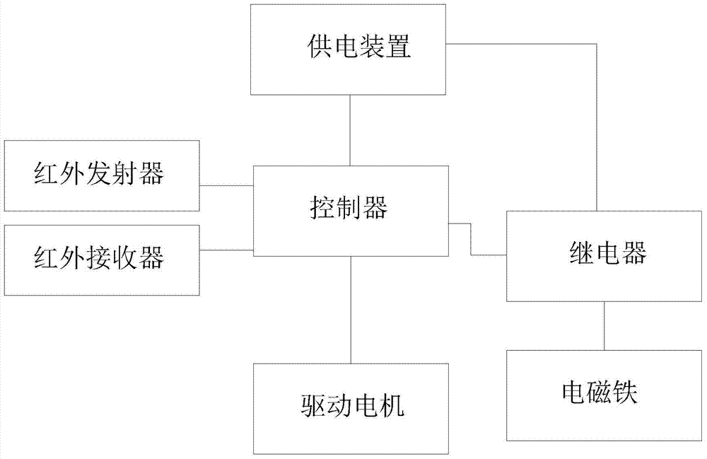
[0030] S2: The controller sends a driving signal to the relay, so that the electromagnet 102 is energized to attract the armature 106, the armature 106 drives the cross bar 105 to move upward, and drives the limit plate 107 to move upward, and the limit plate 107 pushes the support rod 109 to move upward, so that the drive gear 113 is fitted on the side wall below...


PUM


Abstract

The invention discloses a pipeline outer wall automatic rust removal device which comprises a support and an electromagnet arranged below the support. Threaded holes distributed at equal intervals are formed in the side walls of the two sides of the support in the height direction. Fixing frames are arranged on the two sides of the support respectively. Through holes are formed in the two fixing frames respectively. Fastening bolts are arranged in the through holes and penetrate through the through holes to be connected into threaded holes in the side walls of the support in a threaded mode. Positioning plates are arranged at the upper ends of the two fixing frames respectively. A cavity is formed between the opposite end faces of the two positioning plates. The width of the cavity is smaller than the diameter of a pipeline. Sweeping brushes are arranged on the opposite end faces of the two fixing frames respectively. The whole structure is driven by a motor to run along the outer wall of the pipeline, and automatic operation can be achieved; meanwhile, the infrared detection mode is adopted, the effect that the pipeline outer wall automatic rust removal device automatically stops when encountering barriers is achieved, the structure is simple, and operation is convenient.

Description

technical field [0001] The invention relates to an automatic derusting device for the outer wall of a pipeline and an automatic derusting method for the outer wall. Background technique [0002] After long-term use, the pipeline is prone to rust stains due to the corrosion of the external environment. In severe cases, it will cause pipeline leakage and affect its use. Contents of the invention [0003] The purpose of the present invention is to provide an automatic derusting device and method for the outer wall of a pipeline, which can improve the problems existing in the prior art, and can realize automatic operation by using a motor to drive the overall structure to run along the outer wall of the pipeline. The detection method achieves the effect of automatically stopping when encountering obstacles, with simple structure and convenient operation. [0004] The present invention is realized through the following technical solutions: [0005] An automatic rust removal d...

Claims


Application Information

Patent Timeline
Patent Type & Authority Patents(China)
IPC IPC(8): B08B9/023
CPCB08B7/024B08B9/023
Inventor 常学玲洪卓升文金花
Owner 石家庄德贤建筑工程有限公司
Why Eureka
Try Eureka