A turning machine for flipping pcb boards

A technology of PCB board and turning machine, which is applied in the field of turning machine, can solve the problems of increased production cost, low production efficiency, and decreased equipment capacity, and achieve the effect of ensuring transportation, ensuring transmission, and improving equipment versatility

Active Publication Date: 2018-07-03
SHENZHEN XING GRAIN AUTOMATION CO LTD
View PDF3 Cites 1 Cited by
  • Summary
  • Abstract
  • Description
  • Claims
  • Application Information

AI Technical Summary

Problems solved by technology

[0003] The connector is an important electronic component on the circuit board of electronic equipment. Its function is to build a bridge of communication between blocked or isolated circuits in the circuit, so that the current can flow and the circuit can realize the predetermined Function, for a large-scale communication base station circuit board, there are multiple connectors on it, and the front and back sides are fixed with connectors. The way the connector is connected to the PCB board is to insert the pins of the connector into the pinholes of the PCB board. , in the actual assembly line production process, the connector is generally automatically connected to the PCB board through crimping equipment, but for the PCB board that needs to fix the connector on both sides, in the assembly line processing process, the PCB board on one side After the connector crimping is completed, when fixing the connector on the other side of the PCB board, the PCB board needs to be removed again, turned over 180°, and then sent to the crimping equipment for crimping. This manufacturing process interrupts the normal assembly line processing , low production efficiency, resulting in a sharp drop in equipment capacity and increased production costs

Method used


Image

  • A turning machine for flipping pcb boards
  • A turning machine for flipping pcb boards
  • A turning machine for flipping pcb boards

Examples


Embodiment Construction

[0027] The present invention will be further described below in conjunction with accompanying drawing:

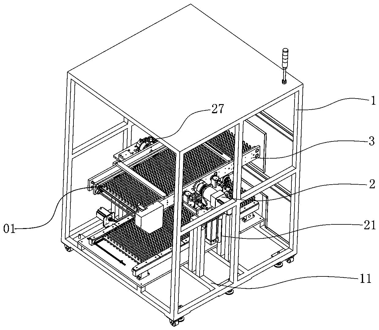
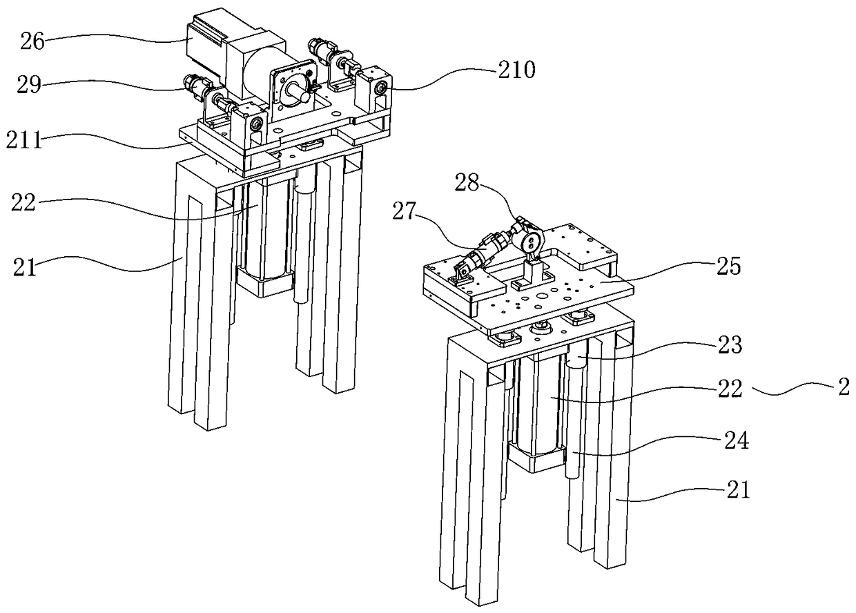
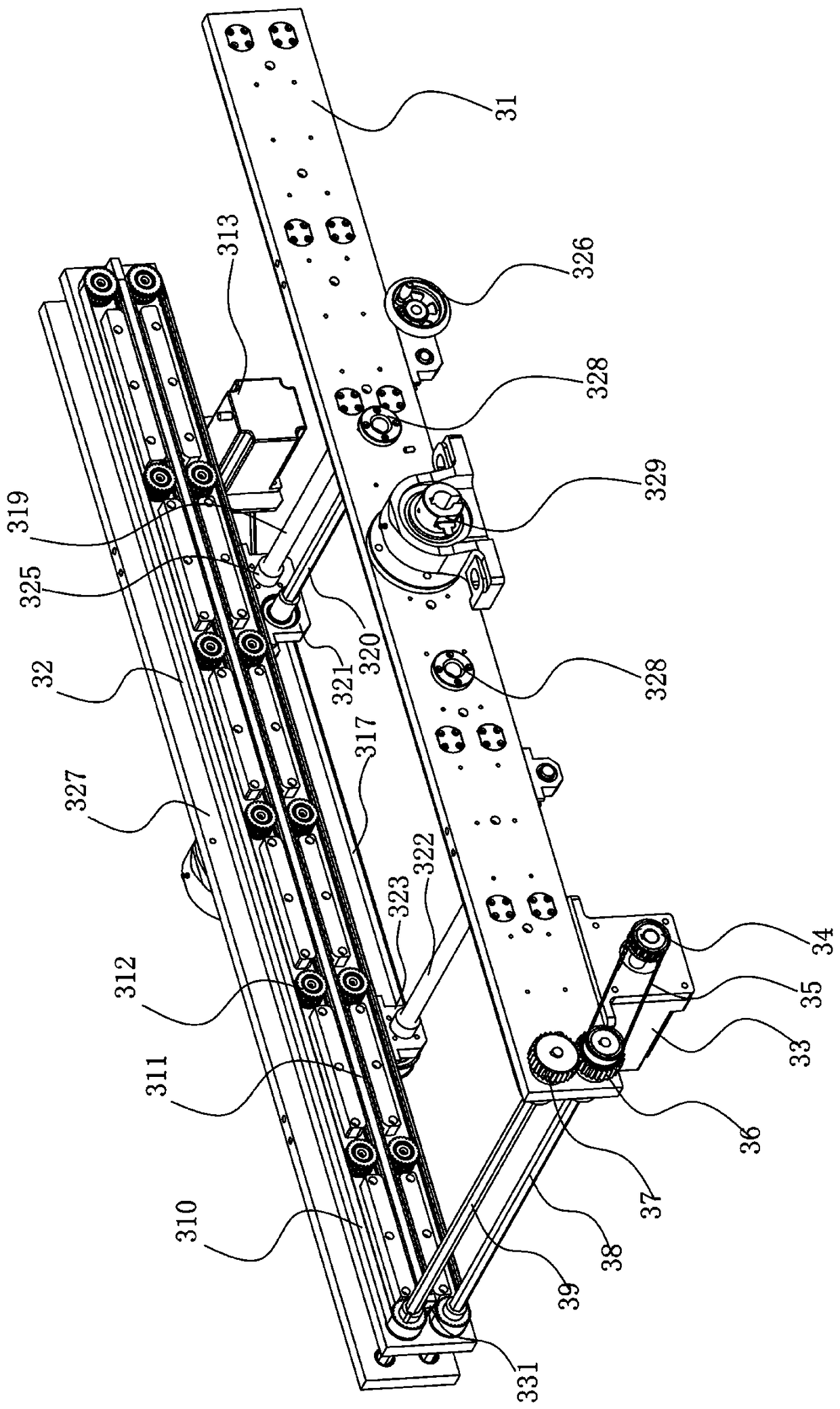
[0028] like Figure 1 to Figure 4 As shown, the technical solution adopted by the present invention is as follows: a panel turnover machine for PCB board turnover, including a frame 1, a turnover support mechanism 2 and a turnover guide mechanism 3, wherein the above-mentioned frame 1 is a frame structure, Both sides of the frame 1 are connected with support rods 11; the above-mentioned overturning support mechanism 2 is fixed on the support rod 11 and extends upwards, and the two sides of the overturning support mechanism 2 are respectively provided with a turning drive motor 26 and a tight cylinder 27; The guide mechanism 3 is arranged between the overturn drive motor 26 and the tight cylinder 27, and is connected with the overturn drive motor 26 and the hold cylinder 27 respectively. The overturn drive motor 26 drives the overturn guide mechanism 3 to rotate 180°, so tha...


PUM


Abstract

The invention discloses a board turnover machine for turning over a PCB. The board turnover machine includes a frame, a turnover supporting mechanism and a turnover material guide mechanism. The frame is of a framework structure. Supporting rods are connected on the two sides of the frame. The turnover supporting mechanism is fixed to the supporting rods and extends upwardly. A turnover drive motor and a clamping cylinder are disposed on the two sides of the turnover supporting mechanism respectively. The turnover material guide mechanism is disposed between the turnover drive motor and the clamping cylinder, and is connected to the turnover drive motor and the clamping cylinder. The turnover drive motor drives the turnover material guide mechanism to rotate 180 degrees to enable the front side and the back side of a PCB on the turnover material guide mechanism to be changed in position. The clamping cylinder clamps the turnover material guide mechanism after turnover. The board turnover machine is integrated in a connector automation streamline to automatically turn over PCBs. The machine is high in automation, enables labor and time to be saved, and helps to greatly improve the production power of the streamline.

Description

technical field [0001] The invention relates to the field of automatic machinery, in particular to a turning machine for turning over PCB boards. Background technique [0002] PCB board, also known as printed circuit board, is based on the circuit schematic diagram to realize the functions required by the circuit user. According to the circuit schematic diagram, the wires are concentrated in a small plate-like structure; PCB board is the most basic The carrier is an indispensable function realization unit for all kinds of electronic products. After the PCB board wiring is completed, according to the functional characteristics of the product, it is necessary to connect various electronic components to the pre-vacant connection holes on the PCB board to form a complete circuit board. [0003] The connector is an important electronic component on the circuit board of electronic equipment. Its function is to build a bridge of communication between blocked or isolated circuits i...

Claims


Application Information

Patent Timeline
Patent Type & Authority Patents(China)
IPC IPC(8): H05K3/30
CPCH05K3/30H05K2203/1563
Inventor 宾兴
Owner SHENZHEN XING GRAIN AUTOMATION CO LTD
Why Eureka
Try Eureka