Laser scanning device with base

A technology of laser scanning and pedestal, which is applied in the field of scanners, can solve problems such as inconvenient maintenance, inability to disassemble in time, and affect work, so as to prevent damage to the engine, not affect work efficiency, and solve placement problems

Active Publication Date: 2018-02-09
江苏扬先科技有限公司
View PDF5 Cites 0 Cited by
  • Summary
  • Abstract
  • Description
  • Claims
  • Application Information

AI Technical Summary

Problems solved by technology

[0003] The scanning head of the laser scanner in the prior art is designed with a concave structure, and more dust will adhere to it during continuous use, so that the laser scanning head will not be able to scan effectively during the scanning process. As a result, laser scanners will be limited after a period of use, and in supermarkets and other large manufacturers or places where laser scanners are used, once the scanning fails or the barcode cannot be scanned, it will directly affect the work and lead to stagnation, resulting in losses; moreover, the engine part and the grip part of the laser scanner are generally designed into an integrated structure, such a structure cannot be disassembled in time for maintenance when the laser head fails, which is inconvenient for maintenance, and the integrated In the structural design, if the laser head is damaged, the grip part can no longer be used, resulting in waste; in addition, the scanner is generally placed directly on the table after use without a stable support base, and it can be used back and forth for a long time Picking up and putting down will cause damage to the engine part

Method used


Image

  • Laser scanning device with base
  • Laser scanning device with base
  • Laser scanning device with base

Examples


Embodiment Construction

[0024] In order to enable those skilled in the art to better understand the technical solution of the present invention, the technical solution of the present invention will be further described below in conjunction with the accompanying drawings and embodiments.

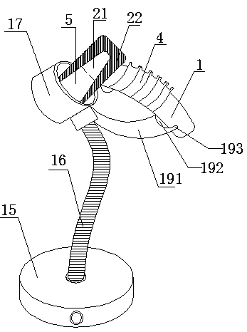
[0025] Refer to attached Figure 1-6 The shown laser scanning device with a base includes a scanner and a base, the scanner is arranged on the base, the scanner includes an engine part 2 and a grip part 1, and the engine part 2 Composed of an engine head 21 and a positioning seat 22, the base includes a suction cup 15, a hose 16 connected to the suction cup 15, a slot 17 fixedly connected to the top of the hose 16, and a support fixed in the middle of the hose 16 , the suction cup 15 is provided with a suction cup button 151, the suction cup 15 can be firmly sucked on the table through the suction cup button 151, a plug is set in the slot, and the engine head of the scanner engine part is inserted into the plug. sl...


PUM


Abstract

The invention discloses a laser scanning device with a base. The laser scanning device comprises a scanner and the base, wherein the scanner comprises an engine part and a holding part; the engine part consists of an engine head and a positioning seat; the base comprises a suction cup, a hose connected to the suction cup, an insertion groove fixedly connected to the top end of the hose, and a supporting part fixed in the middle of the hose; an insertion column is arranged in the insertion groove; the engine head further comprises a laser scanning window that is recessed inwards; a dust removal mechanism is arranged at the upper end of a scanning head of the laser scanning window; and a longitudinal sliding mechanism is arranged on the side surface of the front end of the laser scanning window. The laser scanning device not only can realize detachable connection between the engine head and the holding part but also can realize automatic dust removal all the time, and the dust removal is simple, convenient and flexible; the service life of the laser scanner is prolonged, the fault rate is reduced, the efficiency is improved, and the loss is reduced; the laser scanning device is high in feasibility, safety and stability; and the problem of damage to the engine part caused by improper arrangement is avoided.

Description

technical field [0001] The invention relates to a scanner, in particular to a laser scanning device with a base. Background technique [0002] The laser scanner is used to record the price, name, item number and other information of the commodity, and scan the barcode optically, which can quickly read the data, reduce a lot of time that originally required manual data entry, and save management and personnel costs. At present, the scanners for reading and barcodes can be divided into two types: fixed and handheld according to the operation mode. Among them, the handheld barcode scanner is a relatively economical and convenient device for reading barcodes. When the scanner reads the barcode, the positional relationship and angle between the scanning head and the barcode label are closely related to whether the barcode data can be read correctly and quickly. [0003] The scanning head of the laser scanner in the prior art is designed with a concave structure, and more dust wi...

Claims


Application Information

Patent Timeline
Patent Type & Authority Patents(China)
IPC IPC(8): G06K7/10
CPCG06K7/10881
Inventor 蔡群林杨彬汪劲松
Owner 江苏扬先科技有限公司
Why Eureka
Try Eureka