Impulse grounding resistance calculation method considering spark discharge effect

A technology of impact grounding resistance and calculation method, applied in the direction of grounding resistance measurement, etc., can solve problems such as slow calculation speed, end oscillation, and difficulty in solving transient characteristics by transmission line method.

Inactive Publication Date: 2016-04-13
STATE GRID CORP OF CHINA +3
View PDF6 Cites 5 Cited by
  • Summary
  • Abstract
  • Description
  • Claims
  • Application Information

AI Technical Summary

Problems solved by technology

[0003] In the traditional method of solving the resistance value of impact grounding resistance, the transmission line method can obtain better results in solving the transient characteristics of horizontal grounding conductors, but for grounding bodies with complex shapes such as tower grounding devices, or vertical grounding electrodes, the transmission line method It is difficult to solve the transient characteristics
[0004] The electromagnetic field method generally needs to subdivide the area where the conductor is located, the calculation speed is slow, and the algorithm may not converge
If the time-domain finite difference algorithm is used, it is difficult to calculate the complex structure conductor; if the finite element algorithm is used, it is necessary to transform the time-domain lightning current into the frequency domain first, and obtain the transient response at each frequency point in the inverse Fourier Transforming to the frequency domain, not only the calculation speed is slow, but also there will be end oscillations
Electromagnetic field methods also have great difficulty considering time-varying properties such as spark discharges

Method used


Image

  • Impulse grounding resistance calculation method considering spark discharge effect
  • Impulse grounding resistance calculation method considering spark discharge effect
  • Impulse grounding resistance calculation method considering spark discharge effect

Examples


Embodiment 1

[0081] Such as Figure 1-4 Shown, the inventive method of this example comprises the following steps:

[0082] 1 Relationship between leakage current and axial current

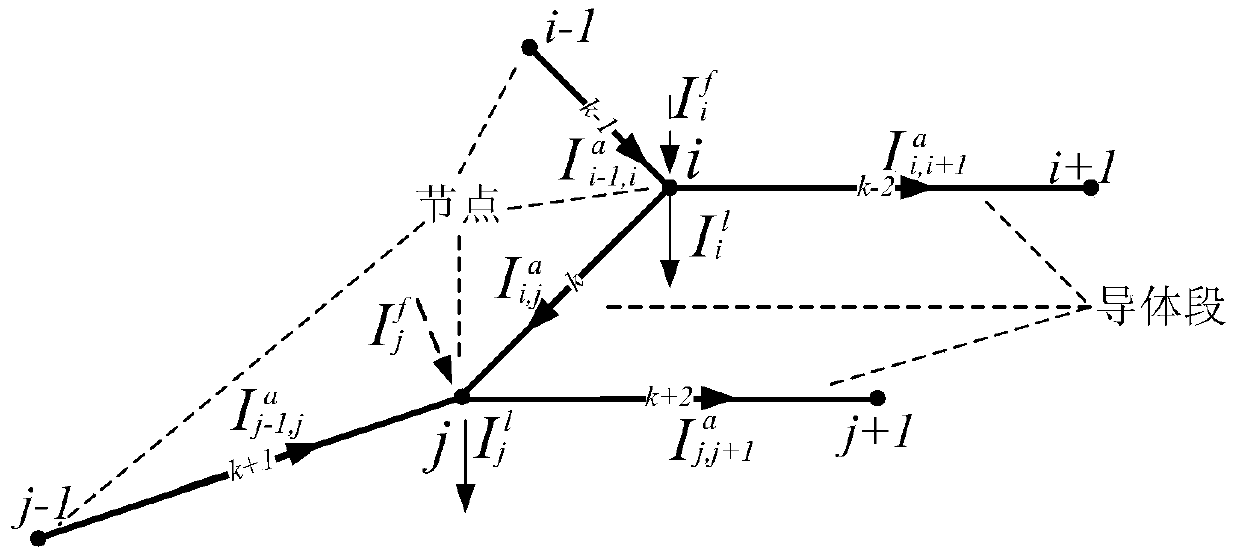
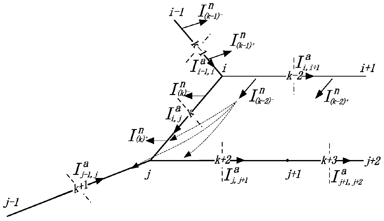
[0083] For complex grounding structures, the nodes satisfy Kirchhoff's current law—the total amount of incoming current at a node is equal to the total amount of outgoing current. The current flowing throughout the conductor and surrounding area is as follows figure 2 shown.

[0084] Assume Indicates the leakage current on node i; Represents the axial current from node i to node j, and there is one and only one conductor segment between node i and node j to associate them; is the injection current of each node i, at the lightning current injection point I f Equal to the injected lightning current, I at the non-current injection point f to zero.

[0085] According to the KCL equation, their relationship can be listed for node i:

[0086] I i l ...


PUM


Abstract

The invention relates to an impulse grounding resistance calculation method considering a spark discharge effect. The method comprises the following steps: respectively determining relations among leakage current, axial current, and node potential of a grounding body conductor; determining the leakage current, axial current, and node potential of the grounding body conductor; determining an equivalent radius of a grounding body conductor segment; determining axial resistance, self-inductance, and frequency-dependent property of the grounding body conductor; determining self-resistance of the grounding body conductor over ground, mutual resistance among conductors, and time-variant characteristic; and determining the relation of the leakage current of the node of the grounding body conductor and the equivalent radius of the conductor segment. An analytical method of combining an electromagnetic field with a circuit is used, an electromagnetic field method is used to solve conductor parameters, and a circuit method is used to solve transient response. The method can adapt to grounding bodies in complex shapes, and can give comprehensive consideration to conditions which may occur in spark discharge effect, inductive effect, potential shielding effect, and other impulse heavy current conditions. Compared with a conventional calculation method, the method is closer to volt-ampere characteristics of a grounding device under an impact condition.

Description

Technical field: [0001] The invention relates to a calculation method of impact grounding resistance, and more particularly relates to a calculation method of impact grounding resistance considering spark discharge effect. Background technique: [0002] The grounding of power system is an important issue directly related to the safety of people, equipment and system. The accuracy of the grounding resistance measurement of the grounding grid is directly related to the correct judgment of the construction quality of the grounding grid and whether the grounding grid in operation meets the project quality requirements. [0003] In the traditional method of solving the resistance value of impact grounding resistance, the transmission line method can obtain better results in solving the transient characteristics of horizontal grounding conductors, but for grounding bodies with complex shapes such as tower grounding devices, or vertical grounding electrodes, the transmission line m...

Claims


Application Information

Patent Timeline
Patent Type & Authority Applications(China)
IPC IPC(8): G01R27/20
Inventor 吴锦鹏张波段舒宁
Owner STATE GRID CORP OF CHINA
Why Eureka
Try Eureka