Shaft kiln burner and method

A technology of vertical kiln and mixing tube, which is applied in the combustion of refractory materials and in the field of vertical kiln burners. It can solve the problems of excess combustion gas, excess fuel, and insufficient combustion of gas, so as to reduce consumption, increase sintering speed, and improve sintering efficiency. quality effect

Inactive Publication Date: 2016-04-13
梁燕龙
View PDF5 Cites 0 Cited by
  • Summary
  • Abstract
  • Description
  • Claims
  • Application Information

AI Technical Summary

Problems solved by technology

[0002] As far as the inventor knows, the combustion device used in the current domestic shaft kiln sintering bauxite process is a diffusion combustion, and the commonly used diffusion combustion is that the gas-supporting gas and the gas are mixed while burning, and there are several disadvantages; the first is because the mixing is not good It will cause excess combustion gas, increase the temperature of the exhaust gas and increase the heat loss of the kiln
Second, due to poor mixing, the gas cannot be fully combusted, resulting in excess fuel, thus wasting fuel
The working method of the burner on the existing design combustion device is to sinter by the external flame under the condition of heat radiation, and at the same time, the highest temperature part is not on the sintered object on the kiln wall, and part of the heat energy is transferred by the inner kiln wall and the sintered object through radiation. It is not directly sintered by flame, so in the actual operation, the fire outlet of the kiln wall is particularly deformed due to sintering. In addition, the temperature inside the kiln wall is higher than the temperature of the sintered object, which is a waste of fuel

Method used


Image

  • Shaft kiln burner and method

Examples


Embodiment Construction

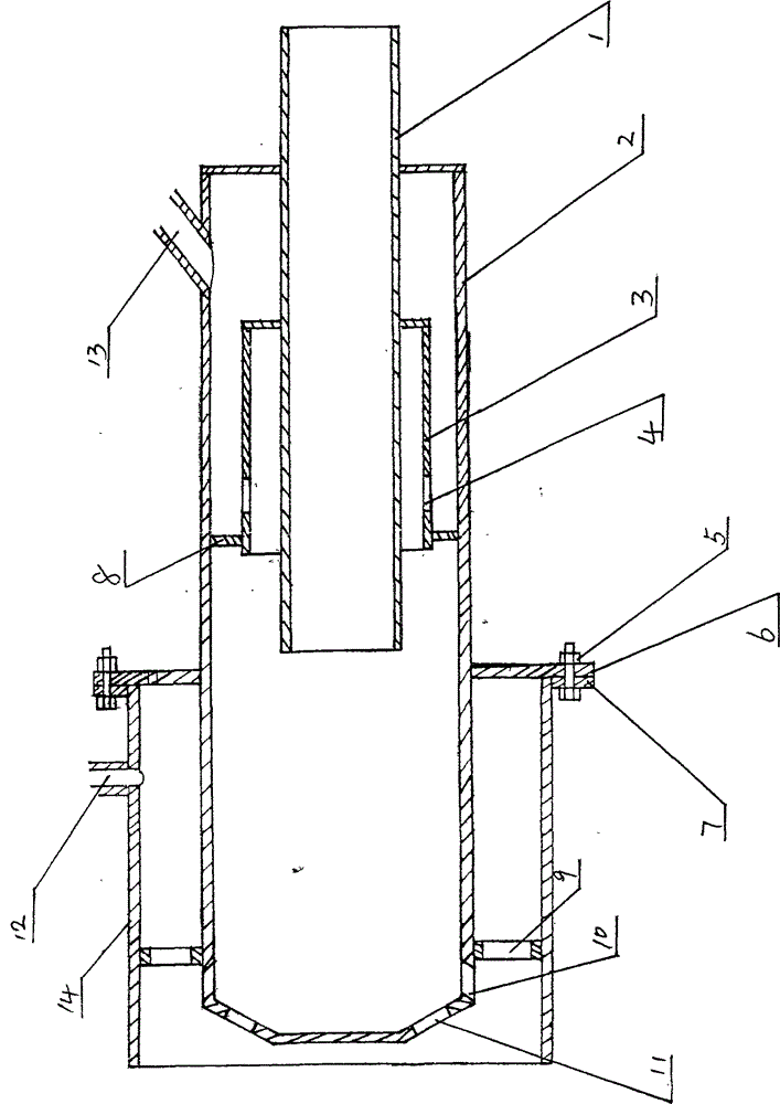
[0008] Such as figure 1 The specific embodiment of shaft kiln burner and method of the present invention shown is characterized in that an air pipe 1 is set, and an air intake pipe 3 is sleeved on the outside of the air pipe 1. There is a gap between the air intake pipe 3 and the air pipe 1, and the air intake pipe 1 3 The front end pipe wall is provided with a gas inlet 4, and the end of the intake pipe 3 close to the gas inlet 4 is provided with a plug 8, the outside of the intake pipe 3 is sleeved with a mixing pipe 2, and the rear wall of the mixing pipe 2 is provided with a gas port 13, The front end wall of the mixing tube 2 is provided with a gas mixing outlet 10, the conical surface of the mixing tube 2 is provided with a gas mixing outlet-a11, the front end wall of the mixing tube 2 is provided with a bracket 9, and the outside of the mixing tube 2 is equipped with a connecting plate 6, The secondary air pipe 14 is set outside the mixing pipe 2, the rear end of the se...


PUM


Abstract

The invention provides a shaft kiln burner and a method. The shaft kiln burner is characterized in that an air pipe (1) is arranged on the shaft kiln burner; an air inlet pipe (3) sleeves the air pipe (1); a gap is reserved between the air inlet pipe (3) and the air pipe (1); a fuel gas inlet (4) is formed in a pipe wall of the front end of the air inlet pipe (3); a plug (8) is arranged at one end, which is close to the fuel gas inlet (4), of the air inlet pipe (3); a mixing pipe (2) sleeves the air inlet pipe (3); a fuel gas opening (13) is formed in a pipe wall of the rear end of the mixing pipe (2); a mixed gas outlet (10) is formed in a pipe wall of the front end of the mixing pipe (2); a mixed gas outlet -a (11) is formed in a conical surface of the mixing pipe (2); a support (9) is arranged on a pipe wall of the front end of the mixing pipe (2); a connecting plate (6) is mounted on the outside of the mixing pipe (2); a secondary air pipe (14) sleeves the mixing pipe (2); a flange (7) is arranged at the rear end of the secondary air pipe (14) and is fixed with the connecting plate (6) through screws (5); and an air opening (12) is formed in a pipe wall of the secondary air pipe (14).

Description

Technical field: [0001] The invention specifically relates to a shaft kiln burner and a method thereof, which belong to the technical field of kiln combustion and are suitable for the combustion application of refractory materials. Background technique: [0002] As far as the inventor knows, the combustion device used in the current domestic shaft kiln sintering bauxite process is a diffusion combustion, and the commonly used diffusion combustion is that the gas-supporting gas and the gas are mixed while burning, and there are several disadvantages; the first is because the mixing is not good It will cause a surplus of supporting gas, increase the temperature of the exhaust gas and increase the heat loss of the kiln. The second is that the gas cannot be fully burned due to poor mixing, resulting in excess fuel, thus wasting fuel. The working method of the burner on the existing design combustion device is to sinter by the external flame under the condition of heat radiation...

Claims


Application Information

Patent Timeline
IPC IPC(8): F27B1/10
Inventor 梁燕龙
Owner 梁燕龙
Why Eureka
Try Eureka