
Automatic strip-cutting machine

A slitter and automatic technology, applied in metal processing and other directions, can solve the problems of low work efficiency, low degree of automation, slow moving speed, etc., and achieve the effect of high cutting efficiency, high precision and fast cutting, and simple structure

Inactive Publication Date: 2016-04-13
SHENGZHOU YIHAI MOTOR PARTS FACTORY
View PDF9 Cites 11 Cited by
  • Summary
  • Abstract
  • Description
  • Claims
  • Application Information

AI Technical Summary

Problems solved by technology

The cloth is generally rolled into a roll by a winding machine, and then cut, but the cutting size of the cloth requires manual operation of the moving device. After moving the moving device to the corresponding distance to be cut, and then operating the cutting device to cut the cloth, this manual The operation mode not only has slow moving speed and low work efficiency, but also the cutting size is not accurate enough; on the other hand, the existing strip cutting machine has complex structure and low degree of automation

Method used

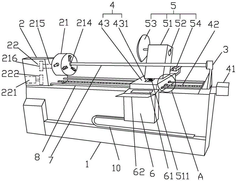

Image

  • Automatic strip-cutting machine
  • Automatic strip-cutting machine
  • Automatic strip-cutting machine

Examples


Embodiment Construction

[0014] The preferred embodiments of the present invention will be described in further detail in conjunction with the accompanying drawings.

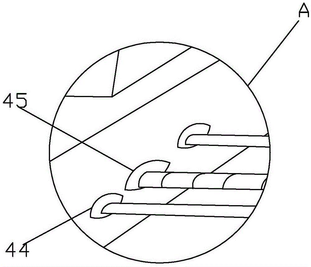
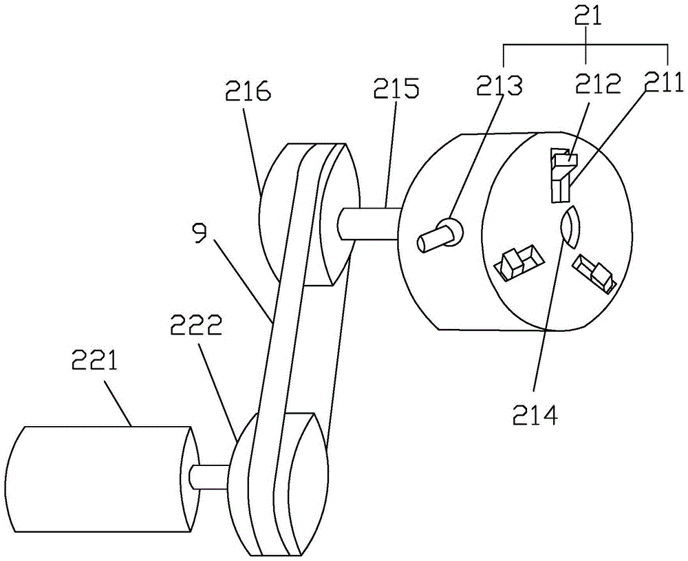
[0015] Such as Figure 1-3 Described a kind of automatic strip cutting machine, comprises frame 1, machine head 2, machine tail 3, moving device 4, cutting device 5 and PLC control box 6, and described machine head 2 and machine tail 3 are respectively positioned at bit frame 1 on both sides, the machine head 2 includes a clamping chuck 21 and a driver 22 that drives the clamping chuck 21 to rotate. The driver 22 adopts a second motor 221, and the main shaft of the second motor 221 is provided with a drive wheel 222, the connecting shaft 215 is provided with a driven wheel 216, and a belt 9 is provided between the driving wheel 222 and the driven wheel 216, which has a simple structure and is convenient to drive. A sleeve rod 7 is arranged between the clamping chuck 21 and the tail 3 , one end of the sleeve rod 7 is fixedly connected w...


PUM


Abstract

The invention mainly discloses an automatic strip-cutting machine. The technical scheme thereof is as follows: the automatic strip-cutting machine comprises a rack, a head, a tail, a moving device, a cutting device and a PLC control cabinet, wherein the head and the tail are located at the two sides of the rack respectively; the head comprises a clamping chuck and a driver driving the clamping chuck to rotate; a sleeve rod is arranged between the clamping chuck and the tail; the moving device comprises a variable-frequency motor connected to one side of the tail, a screw rod connected with the variable-frequency motor, and a slide plate matching with the screw rod; two guide rails are arranged on the rack, and located between the head and the tail; the screw rod is installed between the guide rails; the variable-frequency motor drives the screw rod to rotate, thus driving the slide plate to move; the cutting device is connected to the top of the slide plate; the cutting device comprises a cutting frame, a first motor, a cutting knife and a cylinder; and a piston rod on the cylinder drives the cutting frame to move back and forth on the slide plate. The automatic strip-cutting machine disclosed by the invention has the advantages of being simple in structure, high in cutting efficiency, convenient to operate, and accurate in cutting.

Description

technical field [0001] The invention relates to the technical field of cutting, in particular to an automatic strip cutting machine. Background technique [0002] The strip cutting machine is a machine used for cutting strips. The strip cutting machine is used for making shoes, clothing, bags, shoes and hats, clothing accessories, medical supplies, reflective material factories, tent factories, umbrella factories, gift packaging, bunting production, decorative accessories It is an essential choice for cutting bundles and cutting (rolling) strips in other industries. The strip cutting machine is also called the cutting and binding machine. It is suitable for garment accessories: non-woven interlining, spunbond interlining, double-sided adhesive interlining, cloth strips, nylon adhesive interlining, shoemaking, cap making, leather, interlining, tape, papermaking , handbags and other industries of different width strips, straight and oblique cutting. The cloth is generally ro...

Claims


Application Information

Patent Timeline
IPC IPC(8): B26D1/15B26D5/04B26D7/02B26D7/26B26D7/28
CPCB26D1/15B26D5/04B26D7/02B26D7/26B26D7/2621B26D7/2635B26D7/28Y02P70/10
Inventor 陈意
Owner SHENGZHOU YIHAI MOTOR PARTS FACTORY
Learn More