
Electric tool rest

A tool holder, electric technology, applied in the direction of large fixed members, metal processing machinery parts, maintenance and safety accessories, etc., can solve the problems of slow heat dissipation of the tool, adhesion and wear of cutting edge workpiece materials, etc., so as to delay loss and reduce processing. The effect of cost and processing parameter optimization

Inactive Publication Date: 2016-04-13
付强
View PDF9 Cites 2 Cited by
  • Summary
  • Abstract
  • Description
  • Claims
  • Application Information

AI Technical Summary

Problems solved by technology

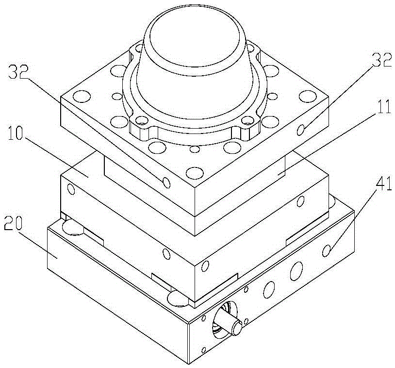
[0003] The purpose of the present invention is to provide an electric tool holder to solve the serious wear caused by the slow heat dissipation of the tool installed on the electric tool holder in the prior art and the problem that the workpiece material is easily bonded on the cutting edge of the tool. question

Method used


Image

  • Electric tool rest
  • Electric tool rest
  • Electric tool rest

Examples


Embodiment Construction

[0042] The technical solutions of the present invention will be clearly and completely described below in conjunction with the accompanying drawings. Apparently, the described embodiments are some of the embodiments of the present invention, but not all of them. Based on the embodiments of the present invention, all other embodiments obtained by persons of ordinary skill in the art without making creative efforts belong to the protection scope of the present invention.

[0043] In the description of the present invention, it should be noted that the terms "center", "upper", "lower", "left", "right", "vertical", "horizontal", "inner", "outer" etc. The indicated orientation or positional relationship is based on the orientation or positional relationship shown in the drawings, and is only for the convenience of describing the present invention and simplifying the description, rather than indicating or implying that the referred device or element must have a specific orientation, ...


PUM


Abstract

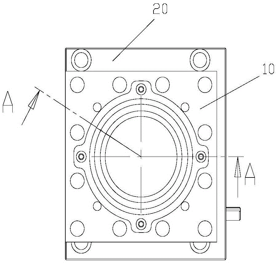
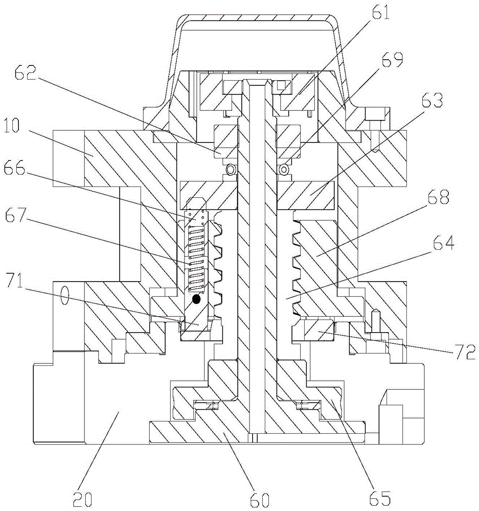
The invention provides an electric tool rest, and relates to the technical field of numerical control machine tools. To solve the problems that a tool installed on an electric tool rest in the prior art is seriously abraded in the using process due to the slow heat dissipation, and workpiece materials are prone to being bonded to a cutting blade of the tool, the electric tool rest comprises an upper tool rest shell, a lower tool rest shell and a rotating mechanism. A plurality of tool installing positions are arranged on the outer surface of the upper tool rest shell, and a plurality of first cooling liquid pipelines are arranged in the upper tool rest shell. Each tool installing position corresponds to at least one first water outlet. The first water outlets are formed in the outer surface of the upper tool rest shell and located above the corresponding tool installing positions. A second cooling liquid pipeline is arranged in the lower tool rest shell, and a second water outlet of the second cooling liquid pipeline can be communicated with any first water inlet. The electric tool rest can cool a tool through the first cooling liquid pipelines and the second cooling liquid pipeline, and the service life of the tool is prolonged.

Description

technical field [0001] The invention relates to the technical field of numerical control machine tools, in particular to an electric tool rest. Background technique [0002] At present, the electric tool post is used in the numerical control machine tool, and is used for clamping the tool to perform the cutting operation on the workpiece. However, during the cutting process, the friction between the tool and the workpiece is severe, and the heat of the tool rises sharply. If the tool is in a high temperature state for a long time, the loss of the tool will be accelerated, and the life of the tool will be shortened, resulting in unstable machining accuracy, and Replacing new tools many times increases the processing cost. In addition, when the tool is performing cutting operations, the cutting edge of the tool is prone to the problem of workpiece material bonding, which affects the machining accuracy of the tool. Contents of the invention [0003] The purpose of the prese...

Claims


Application Information

Patent Timeline
Patent Type & Authority Applications(China)
IPC IPC(8): B23B21/00B23Q1/25B23Q11/00B23Q11/10
CPCB23Q1/25B23Q11/0003B23Q11/02B23Q11/1076
Inventor 付强付娆
Owner 付强
Learn More