
High-positioning-precision photoetching object lens frame with replaceable lens

A technology of positioning accuracy and lithography objective lens, which is applied in the direction of optics, optical components, optomechanical equipment, etc., can solve the problems of large operating space, low positioning and repeat positioning accuracy, complex structure, etc., and achieve the effect of high positioning accuracy

Active Publication Date: 2016-04-06
BEIJING GUOWANG OPTICAL TECH CO LTD
View PDF7 Cites 0 Cited by
  • Summary
  • Abstract
  • Description
  • Claims
  • Application Information

AI Technical Summary

Problems solved by technology

[0004] The purpose of the present invention is to propose a lithography objective lens frame with replaceable lens of high positioning accuracy, which solves the problems of complex structure, large operating space, low positioning and repeat positioning accuracy and easy contamination of the lens in the prior art

Method used


Image

  • High-positioning-precision photoetching object lens frame with replaceable lens
  • High-positioning-precision photoetching object lens frame with replaceable lens
  • High-positioning-precision photoetching object lens frame with replaceable lens

Examples


Embodiment Construction

[0028] Embodiments of the present invention will be further described below in conjunction with the accompanying drawings.

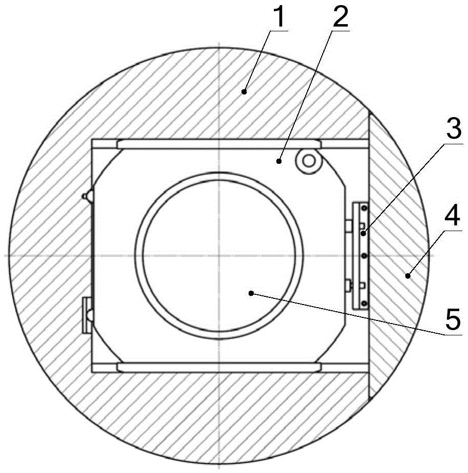
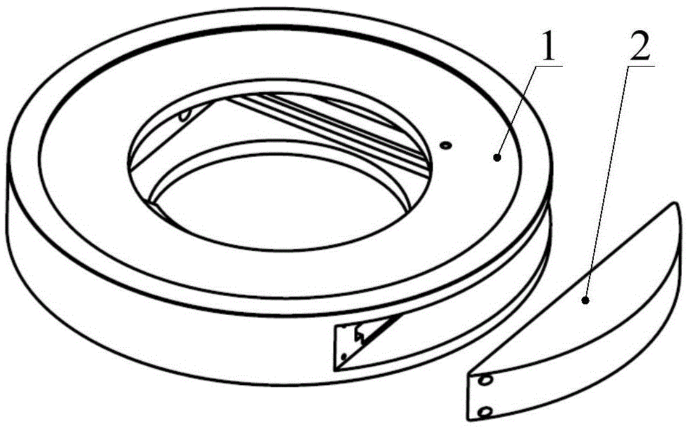
[0029] See attached figure 1 And attached figure 2 , the replaceable lithography objective lens frame of the high positioning accuracy lens of the present invention comprises an outer mirror frame 1, an inner mirror frame 2 and a protective cover 4;

[0030] See attached image 3 And attached Figure 4 , the outer mirror frame 1 is a cylindrical structure, and the inside of the outer mirror frame 1 is a square space, and the mirror frame has an opening opposite to any side wall of the square space, and the two sides of the square space perpendicular to the opening The wall is provided with a chute 102, one end of the side wall of the square space opposite to the opening is provided with a conical groove 104, and the other end is provided with a V-shaped groove 103, and the V-shaped groove 103 is connected to the upper end surface of the outer mirror ...


PUM


Abstract

The invention discloses a high-positioning-precision photoetching object lens frame with a replaceable lens, belongs to the technical field of deep ultraviolet projection photoetching object lens structure design, and aims at solving problems in the prior art that a conventional structure is complex, the operation space is large, the positioning and repeated positioning precision is low and the lens is liable to be polluted. An outer lens frame is in a cylindrical structure, and two inner side walls of the outer lens frame are respectively provided with a chute. An inner side wall is provided with a conical groove and a V-shaped groove, and one end, close to an opening, of the upper end face of the interior of the outer lens frame is provided with a ball head A. An inner lens frame is in a square structure, and any two opposite side walls are provided with sliding rails. One side wall, adjacent to the side wall where the sliding rail is located, is provided with two ball heads B. The positions of the two head balls B are respectively opposite to the conical groove and the V-shaped groove. A part, corresponding to the ball head A, of the upper end face of the square structure is provided with an upper platform. The sliding rails of the inner lens frame cooperate with the chutes in the outer lens frame. An outer side of the inner lens frame is provided with a protection cover, and the protection cover is fixedly connected with the outer lens frame through a screw.

Description

technical field [0001] The invention belongs to the technical field of structural design and assembly of a deep ultraviolet projection lithography objective lens, and in particular relates to a lithography objective lens frame for the refinement, maintenance, replacement and repeated positioning of optical elements in a lithography projection objective lens system. Background technique [0002] Projection lithography objective lens is the key equipment for manufacturing large-scale integrated circuits. In recent years, with the continuous subdivision of the characteristic line width of integrated circuits, the resolution of the projection lithography objective lens has gradually increased. At present, the ArF excimer laser projection lithography equipment with a wavelength of 193.368nm has become the standard for integrated circuit manufacturing at 90nm, 65nm and 45nm nodes. mainstream equipment. The projection lithography objective lens system has extremely high requiremen...

Claims


Application Information

Patent Timeline
Patent Type & Authority Applications(China)
IPC IPC(8): G02B7/02G03F7/00
CPCG02B7/023G03F7/70241
Inventor 陈华男郭抗倪明阳李显凌张巍隋永新杨怀江
Owner BEIJING GUOWANG OPTICAL TECH CO LTD
Learn More