
Active air-chamber structure and photoacoustic spectrometry gas sensing system

A technology of photoacoustic spectroscopy and gas sensing, which is applied in the direction of material analysis, measuring devices, instruments, etc. through optical means, can solve the problems of light source coupling and beam adjustment process complexity, poor stability, etc., to achieve improved optical power and structural stability Sex, reduce beam divergence, and facilitate extraction

Inactive Publication Date: 2016-04-06
武汉精昱光传感系统研究院有限公司
View PDF6 Cites 10 Cited by
  • Summary
  • Abstract
  • Description
  • Claims
  • Application Information

AI Technical Summary

Problems solved by technology

[0005] The technical problem to be solved by the present invention is to provide an integrated light source type active gas chamber structure and photoacoustic spectrum gas transmission for the problems of complex light source coupling and beam adjustment process and poor stability existing in the existing gas chamber / gas pool. Inductive system, which greatly improves the injected light power, and at the same time simplifies the beam adjustment structure, realizes the miniaturization of the gas chamber and improves the stability

Method used


Image

  • Active air-chamber structure and photoacoustic spectrometry gas sensing system
  • Active air-chamber structure and photoacoustic spectrometry gas sensing system

Examples


Embodiment Construction

[0018] In order to make the object, technical solution and advantages of the present invention clearer, the present invention will be further described in detail below in conjunction with the accompanying drawings and embodiments.

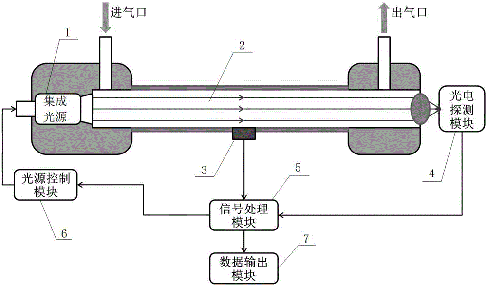
[0019] refer to figure 1 As shown, the active gas chamber structure and photoacoustic spectroscopy gas sensing system in this embodiment include a near-infrared DFB semiconductor laser 1, a photoacoustic cell 2, a microphone 3, a photoelectric detection module 4, a signal processing module 5, and a light source control Module 6 and data output module 7, the near-infrared DFB semiconductor laser 1 is directly packaged with one end of the photoacoustic pool 2 to form a photoacoustic gas chamber with a dumbbell-shaped structure as a whole (this structure can make the photoacoustic signal only propagate along the longitudinal direction, and the There is almost no change in the radial and angular directions, which is beneficial to the detection of photo...


PUM


Abstract

The invention discloses an active air-chamber structure and photoacoustic spectrometry gas sensing system. The active air-chamber structure and photoacoustic spectrometry gas sensing system comprises an integrated light source, a photoacoustic cell, a microphone, a photoelectric detection module, a signal processing module, a light source control module and a data output module; the integrated light source and one end of the photoacoustic cell are directly packaged into a whole, and the microphone is installed on the side wall of the photoacoustic cell; the photosensitive surface of the photoelectric detection module is aligned to a light emitting port of the photoacoustic cell, the output end of the photoelectric detection module and the output end of the microphone are both connected to the input end of the signal processing module, one output end of the signal processing module is connected with the light source control module, the other output end of the signal processing module is connected with the data output module, and the light source control module is connected with the control end of the integrated light source. According to the active air-chamber structure and photoacoustic spectrometry gas sensing system, the structural design of directly packaging a specially designed DFB semiconductor laser and one end of an air chamber into a whole is adopted, the intermediate link of coupling with optical fibers is omitted, and the injected light power is greatly increased; meanwhile, the light beam adjustment structure is simplified, and air chamber miniaturization and stability improvement are achieved.

Description

technical field [0001] The invention relates to a sensing unit structure in the field of gas detection and light sensing, in particular to an integrated light source type active gas chamber structure and a photoacoustic spectrum gas sensing system. Background technique [0002] In recent years, with the maturity and growth of the optical communication industry, the cost of a large number of high-performance optical devices has been continuously reduced, especially the semiconductor DFB lasers in the near-infrared communication band (800-1700nm), whose output power and linewidth characteristics have been greatly improved. promote. It makes it possible to realize the high precision and online monitoring urgently needed by modern industrial applications. Photoacoustic spectroscopy is a detection technology without background signal, which has the advantages of not consuming gas samples, high sensitivity, short detection time, and convenient on-site detection. For very low con...

Claims


Application Information

Patent Timeline
IPC IPC(8): G01N21/01G01N21/17
CPCG01N21/1702G01N21/01
Inventor 李玉林黎敏邓硕
Owner 武汉精昱光传感系统研究院有限公司
Learn More