
Displacement Adjustment Method of Hole Distance of High Precision Composite Gauges

A combined gauge and displacement adjustment technology, applied in the direction of mechanical clearance measurement, etc., can solve the problems of bottom hole surface quality error, interference size error, fitter assembly qualified difficulty, etc.

Active Publication Date: 2018-04-24
CHANGAN AUTOMOBILE (GRP) CO LTD
View PDF5 Cites 0 Cited by
  • Summary
  • Abstract
  • Description
  • Claims
  • Application Information

AI Technical Summary

Problems solved by technology

[0003] For large and extra-large high-precision hole distance gauges with position accuracy within Ф0.004mm, it is quite difficult for fitters to assemble them qualified
This difficulty mainly comes from four aspects: one is the error in the amount of interference required when the measuring column or measuring sleeve is pressed into the bottom hole; the other is the position accuracy error of the bottom hole itself; the third is the error of the surface quality of the bottom hole; It is the bottom hole that cannot be repositioned for processing
Therefore, according to the general processing method, when encountering a hole distance gauge with high precision (the hole distance position accuracy is within 0.004mm or the hole position accuracy is within ±0.002mm), the size adjustment is very difficult, and even the accuracy requirements cannot be met.

Method used


Image

  • Displacement Adjustment Method of Hole Distance of High Precision Composite Gauges
  • Displacement Adjustment Method of Hole Distance of High Precision Composite Gauges
  • Displacement Adjustment Method of Hole Distance of High Precision Composite Gauges

Examples


Embodiment

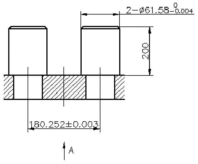
[0017] This embodiment takes figure 1 Take the two-hole position gauge shown as an example. The hole distance of the tested gauge is 180.262mm, the tolerance is 0.007mm larger, and the measuring column at the right end is 89°59′48″ relative to the bottom surface, the angle error is 12″, and the error direction is To the left, in order to make the measuring tool meet the design requirements, the "hole distance displacement adjustment method" of the present invention is used for adjustment. The specific steps are as follows:

[0018] Step 1: Select the left measuring column with relatively good perpendicularity to the bottom surface of the assembly as the positioning reference. It is necessary to adjust the right measuring column to the left along the dimension direction by 0.007-0.01mm, and at the same time ensure that the verticality is within 0.006mm;

[0019] Step 2: Use a diamond file or oil stone to press the right measuring column into the end of the bottom hole, and trim...


PUM


Abstract

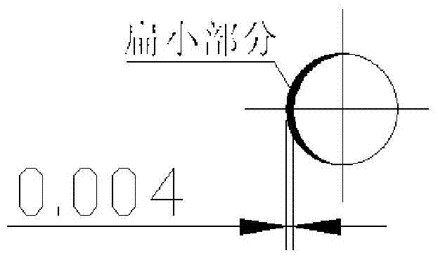
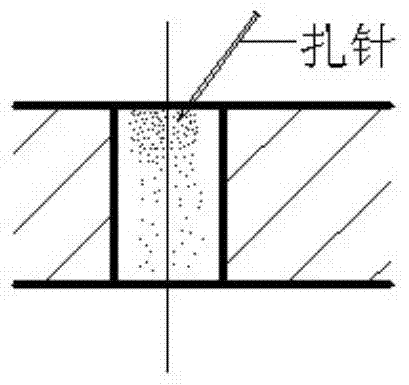
The invention discloses a high precision combined gauge pitch displacement adjusting method, which comprises the steps of a. selecting a left side gauge column having a good verticality with an assembling bottom as a positioning reference, and adjusting a right side gauge column leftwards along the dimension direction for 0.007-0.01mm, and guaranteeing the verticality is controlled within 0.006mm; b. reducing about half area of the left side surface outer round surface of the end of the right side gauge column pressed into a bottom hole with a diamond file or an oilstone so as to reduce the diameter by 0.004-0.006mm; c. pricking multiple protuberant points at the right side surface of the bottom hole with a specially-produced needle so as to enhance the pressure on the bottom hole surface; and d. pressing a finished gauge column into the bottom hole for measurement, and determining if the steps a to c shall be repeated based on the measurement result until the gauge examination is qualified. The method is simple and practical, and can be used for comprehensive debug for two-hole or multi-hole and inclined hole high precision pitch position accuracy gauge.

Description

technical field [0001] The invention belongs to the technical field of mechanical processing, and in particular relates to a method for adjusting the hole distance displacement of a high-precision combined gauge used by a tool fitter when assembling and debugging a high-precision hole distance gauge. Background technique [0002] At present, in the tooling manufacturing, the hole distance gauge is processed by a boring machine, a jig mill or a wire cutting machine for the bottom hole, and then the fitter presses the measuring column or the measuring sleeve into the bottom hole for assembly and debugging. For high-precision hole distance gauges with small dimensions and small apertures, it can also be completed by fitter assembly and debugging after grinding the holes. [0003] For large and extra-large high-precision hole distance gauges with position accuracy within Ф0.004mm, it is quite difficult for fitters to assemble them qualified. This difficulty mainly comes from fo...

Claims


Application Information

Patent Timeline
Patent Type & Authority Patents(China)
IPC IPC(8): G01B5/14
CPCG01B5/14
Inventor 韩小斌
Owner CHANGAN AUTOMOBILE (GRP) CO LTD
Learn More