
Superconductor fiber heat transfer device

A technology of superconducting fibers and heat pipes, applied in heat transfer modification, heat exchange equipment, heat exchanger types, etc., can solve the problems of inability to restart, poor stability, poor heat transfer effect of gravity heat pipes, etc., and achieves no need for daily maintenance. , Simple and safe to use

Active Publication Date: 2016-04-06
ZHEJIANG LUTE ENERGY TECH
View PDF7 Cites 2 Cited by
  • Summary
  • Abstract
  • Description
  • Claims
  • Application Information

AI Technical Summary

Problems solved by technology

[0004] The above-mentioned scheme solves the problem of poor heat conduction effect of the existing gravity heat pipe to a certain extent, but the scheme still exists: poor stability, low heat conduction efficiency, and problems that cannot be restarted after the nano-particles settle and agglomerate

Method used


Image

  • Superconductor fiber heat transfer device
  • Superconductor fiber heat transfer device
  • Superconductor fiber heat transfer device

Examples


Embodiment Construction

[0022] The present invention will be further described in detail below with reference to the drawings and specific embodiments.

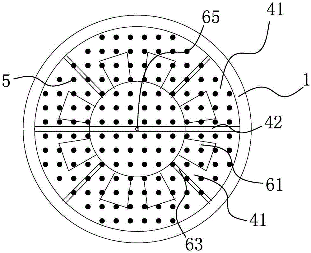
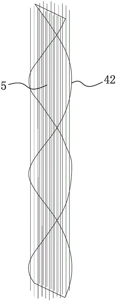
[0023] Such as Figure 1-4 As shown, the present superconducting fiber heat transfer device includes a hollow heat conducting tube body 1 with an inner cavity and closed at both ends. At one end of the hollow heat conducting tube body 1, a working fluid inlet 11 and a working fluid outlet 12 are respectively provided, and the working fluid inlet 11 The upper part is provided with a working fluid inlet heat exchanger 2, and the working fluid outlet 12 is correspondingly provided with a working fluid outlet heat exchanger 3, and the hollow heat-conducting pipe body 1 is provided with a heat-conducting working fluid that can conduct heat after flowing in from the working fluid inlet 11 After the working fluid is guided to the other end of the hollow heat-conducting pipe body 1 and flowing out from the working fluid outlet 12, the hollow heat-conducting pi...


PUM


Abstract

The invention belongs to the technical field of heat conduction devices, and particularly relates to a superconductor fiber heat transfer device. The superconductor fiber heat transfer device solves the technical problem that an existing heat transfer device is low in heat exchange efficiency. The heat transfer device comprises a hollow heat conduction pipe body which is provided with an inner container and two closed ends, a working medium inlet is formed in one end of the hollow heat conduction pipe body, and a working medium outlet is formed in the other end of the hollow heat conduction pipe body; a working medium inlet heat exchanger is correspondingly arranged on the working medium inlet, and a working medium outlet heat exchanger is correspondingly arranged on the working medium outlet; a flow guide structure is arranged in the hollow heat conduction pipe body, and according to the flow guide structure, when heat conduction working media flow in the pipe body from the working medium inlet, the heat conduction working media are guided to the other end of the hollow heat conduction pipe body and then flow out of the pipe body from the working medium outlet; and a plurality of carbon fiber filaments which are located in an inner cavity and made of carbon fiber materials are arranged in the hollow heat conduction pipe body. The heat transfer device has the advantages that externally-provided conveying power can be reduced to the zero, nano particles are suspended and / or accumulated in a nearby manner, use is easy and safe, and daily maintenance is not needed.

Description

Technical field [0001] The invention belongs to the technical field of heat conduction equipment, and particularly relates to a superconducting fiber heat transfer device. Background technique [0002] Heating, cooling, and heat conduction transfer heat energy from side A to side B is a basic process widely used in daily life and in various fields of industry and agriculture. The common heat conduction methods are as follows; first, the wall-type heat conduction under the action of temperature difference; second, the transmission of heat energy in a fluid medium or continuous solid material; and third, the superheat in the form of light / acoustic / electromagnetic waves. Spread by contact. Among them, the method of transporting heat energy to a certain distance through fluid is the most commonly used. The advantage is that the fluid medium can be selected in a wide range, and the distribution and confluence is flexible. The disadvantage is that the conveying process requires exter...

Claims


Application Information

Patent Timeline
Patent Type & Authority Applications(China)
IPC IPC(8): F28D17/00F28F9/22F28F13/12
CPCF28D17/005F28F9/22F28F13/125F28F2009/222F28F2255/20
Inventor 夏惊涛代伯清陈雷娟
Owner ZHEJIANG LUTE ENERGY TECH
Learn More