
A new dual-purpose valve

A valve, dual-purpose technology, applied in the direction of lift valve, valve device, filtration and separation, etc., can solve the problems of affecting the normal operation of the valve, no filtering function, damage to the precision of the instrument, etc., to prolong the effective water filtration time, the overall structure Simple and practical, less maintenance work

Active Publication Date: 2018-05-22
QINGDAO HUAGUAN VALVE CO LTD
View PDF8 Cites 0 Cited by
  • Summary
  • Abstract
  • Description
  • Claims
  • Application Information

AI Technical Summary

Problems solved by technology

At present, the filtration appears in front of people with large-scale filtration systems, but for workshops or enterprises with a small amount of sewage, it is very wasteful to filter resources, so it is very important to study a small pressure filter that can partially treat some sewage
Existing valves generally do not have a filtering function, and the liquid circulates in the pipeline. Due to the environment or the influence of metal pipelines during transportation, granular impurities are likely to be produced in the circulating medium, and these impurities flow through the pipeline continuously with the medium. Each component in the pipeline is easy to cause wear to the valves in the pipeline, and damage the precision of instruments such as water meters with high sensitivity, which will seriously affect the normal operation of the valves, and eventually lead to failures in the pipeline system, reducing its service life and increasing Maintenance costs

Method used


Image

  • A new dual-purpose valve
  • A new dual-purpose valve
  • A new dual-purpose valve

Examples


Embodiment 1

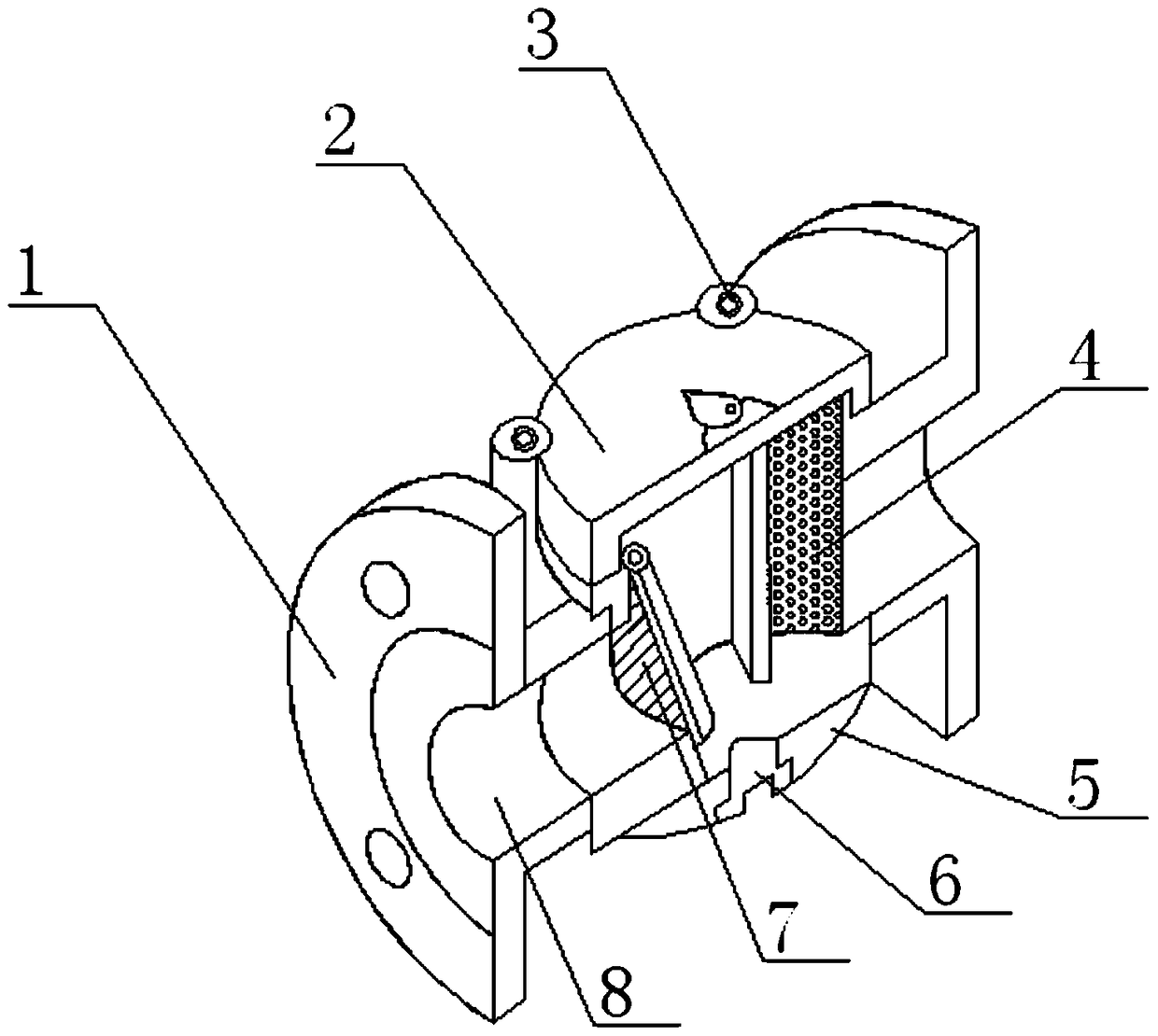
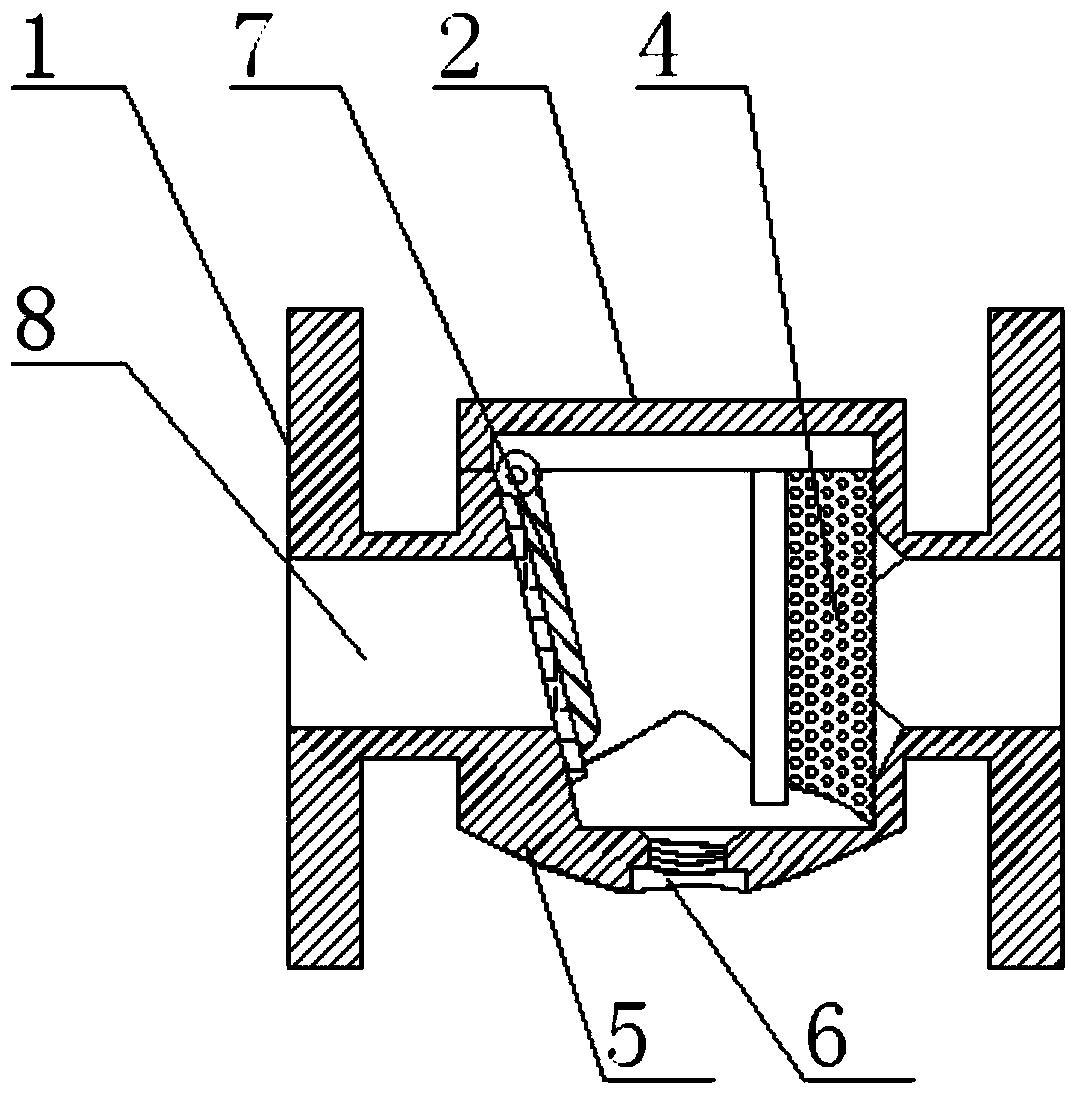
[0030] Such as figure 1 and figure 2 As shown, a new dual-purpose valve includes a valve body, a valve cover, a filter screen and a valve plate. Symmetrical flanges are arranged at both ends of the valve body, and the symmetrical flanges are connected through cylindrical pipes. The upper end of the middle part of the valve body is provided with For the valve cover, there are four symmetrical bolt holes around the upper end of the valve body opposite to the valve cover. A valve plate and a filter screen are provided, and the top of the valve plate is movably connected to the valve wall in the middle of the valve body. The movable connection of the valve plate adopts a pin connection or a hinge connection. The liquid inlet port and the liquid outlet port of the pipeline, the valve plate is an integral structure bonded by a gate plate and a rubber sealing plate, the rubber sealing plate is set facing the liquid inlet port, the filter net, etc. There are filter holes at interva...

Embodiment 2

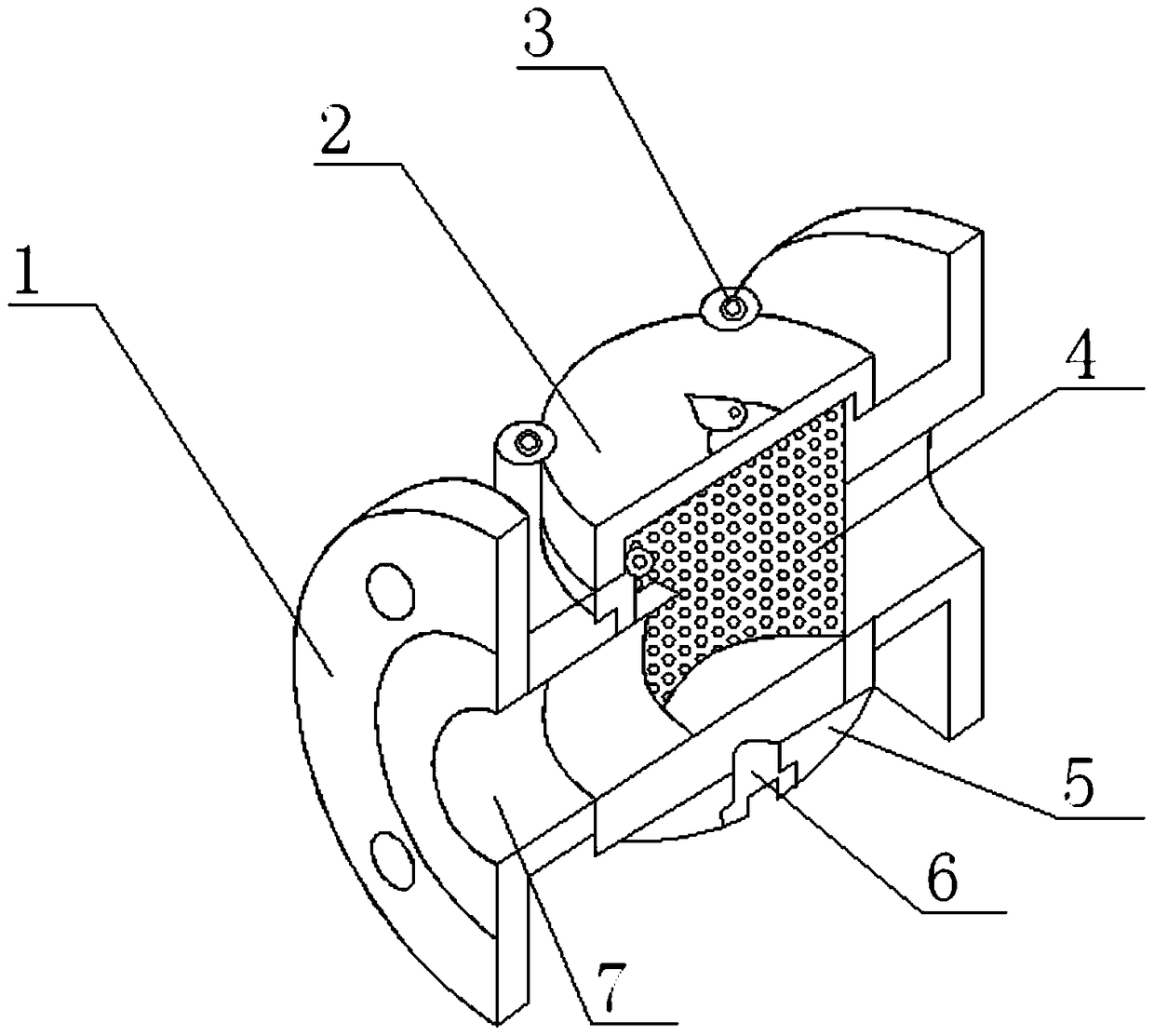
[0033] Such as image 3 and Figure 4 As shown, a new dual-purpose valve includes a valve body, a valve cover and a filter screen. Symmetrical flanges are arranged at both ends of the valve body, and the symmetrical flanges are connected through cylindrical pipes. Four symmetrical bolt holes are arranged around the upper end of the valve body opposite to the bonnet. The bolts are tightly engaged in the bolt holes through the gaskets to tightly connect the bonnet and the valve body. The bonnet is connected to the valve body through bolts. The inside of the valve body at the lower end of the cover is provided with a filter screen, and the filter screen is set as a hollow cylinder structure (such as Figure 5 As shown), the filter screen is provided with filter holes at equal intervals, and the upper and lower ends of the filter screen are respectively connected with the upper and lower valve walls of the valve body to separate the valve body into two cavities. The liquid inlet...


PUM


Abstract

The invention discloses a novel dual purpose valve. The two ends of a valve body are provided with symmetrical flanges which are communicated through a cylindrical pipeline, the upper end of the middle of the valve body is provided with a valve deck which is connected with the valve body through a bolt, a valve plate and a filter screen which are arranged at a liquid inlet end and a liquid outlet end of the cylindrical pipeline respectively are arranged inside the portion, at the lower end of the valve deck, of the valve body, a drain outlet is formed in the valve bottom under the valve deck, and a drain plug is installed in the drain outlet. The valve plays two roles of combing a gate valve with a filtering valve and isolating the gate valve from the filtering valve, the cylindrical pipeline is divided into three cavities, the valve plate can bear pressure, the anti-counter-flow effect of the valve can be achieved, the flow capacity can be controlled, and the overall structure is simple and practical. Under the filtration function of the filter screen, impurities in liquid are discharged through the drain outlet formed in the valve bottom, the filtration capacity is high, the volume is small, setting of the equipment is achieved, the maneuverability of use is great, and the novel dual purpose valve can be suitable for local processing of some sewage.

Description

technical field [0001] The invention belongs to the technical field of valve equipment, and in particular relates to a novel dual-purpose valve. Background technique [0002] A valve is a mechanical device that controls the flow, flow direction, pressure, temperature, etc. of a flowing fluid medium, and a valve is a basic component in a piping system. Valve fittings are technically the same as pumps and are often discussed as a separate category. The valve can be operated manually or by handwheel, handle or pedal, and can also be controlled to change the pressure, temperature and flow of the fluid medium. Valves can operate continuously or repeatedly in response to these changes, such as safety valves installed in hot water systems or steam boilers. In more complex control systems, automatic control valves are used according to the needs of external inputs. Valves are also divided into cast iron valves, cast steel valves, stainless steel valves, chrome molybdenum steel va...

Claims


Application Information

Patent Timeline
Patent Type & Authority Patents(China)
IPC IPC(8): F16K1/32F16K1/36B01D35/04
CPCB01D35/04B01D2201/167F16K1/32F16K1/36
Inventor 纪学清王洪蛟李学洪
Owner QINGDAO HUAGUAN VALVE CO LTD
Learn More