
Cloth cutting device

A technology of cutting device and cloth pressing device, which is applied in the cutting of textile materials, textile and paper making, metal processing, etc. It can solve the problems of easy injury to operators, increased cost of blades, and low level of automation, so as to increase service life and safety High performance, easy and convenient adjustment, and high level of automation

Inactive Publication Date: 2016-04-06
SHENGZHOU YIHAI MOTOR PARTS FACTORY
View PDF8 Cites 24 Cited by
  • Summary
  • Abstract
  • Description
  • Claims
  • Application Information

AI Technical Summary

Problems solved by technology

[0002] The cloth needs to be cut and divided before processing in order to achieve the sewing effect. The existing cloth is generally stored in a roll shape, and the cloth needs to be cut and divided into the required size to meet the production requirements. The cloth cutting is mainly done by scissors. This method is easy to deviate from the track during cutting, which affects the cutting effect. In serious cases, it may directly lead to the scrapping of the fabric, and the edge of the fabric cut by ordinary scissors is not neat, the speed is slow, the labor intensity is high, and the cutting efficiency is high. Low
Later, people used cutting devices to cut the cloth, but the existing cutting machine has complex structure, low automation level, it is inconvenient to adjust the cutting width of the cloth, and the cloth is easy to deviate during transmission.
On the other hand, the cutting knives of existing cutting devices are generally exposed outside, which is easy to injure the operator. The cloth is also easily cut by the cutting knife during the transmission process, and after long-term erosion of water vapor and oxygen in the air, it is easy to rust, causing the blade Dull, requiring frequent replacement of blades, resulting in increased cost of blades

Method used


Image

  • Cloth cutting device
  • Cloth cutting device
  • Cloth cutting device

Examples


Embodiment Construction

[0018] The preferred embodiments of the present invention will be described in further detail in conjunction with the accompanying drawings.

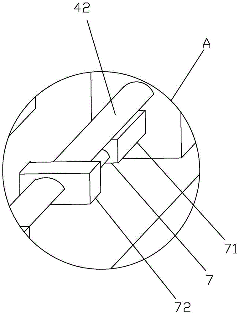
[0019] Such as Figure 1-5 The cloth cutting device described above comprises a cutting table 1, a cutter 2 and an electric control box 3, the right side of the cutting table 1 is provided with a cloth releasing device 4 and a cloth pressing device 5, and the left side of the cutting table 1 is provided with There is a cloth receiving device 6, and the cloth releasing device 4 includes a cloth releasing frame 41 and a cloth releasing roller 42 connected to the cloth releasing frame 41, and the cloth pressing device 5 includes a cloth pressing frame 51 and a cloth pressing frame 51 transferred 51, the pressure roller 52 on the cloth pressure roller 52 is provided with a heater, and the cloth receiving device 6 includes a cloth receiving frame 61, a cloth receiving roller 62 transferred on the cloth receiving frame 61 and a driving cloth ...


PUM


Abstract

The invention mainly discloses a cloth cutting device. According to the technical scheme, the cloth cutting device comprises a cutting table, a cutter and an electric control cabinet. A cloth releasing device and a cloth pressing device are arranged on the right side of the cutting table. A cloth collecting device is arranged on the left side of the cutting table. Sliding rods are arranged on both the front side and the rear side of the cutting table. A sliding frame is arranged on the sliding rods and comprises sliding bases and a rodless air cylinder. The sliding bases are movably connected with the sliding rods. The rodless air cylinder is installed between the sliding bases. A magnet ring sleeve is arranged outside the rodless air cylinder. The cutter is connected to the magnet ring sleeve and comprises a cutting base and a cutting knife. The cutting base is connected with the magnet ring sleeve. A containing cavity is formed in the cutting base. A miniature air cylinder is arranged on the inner wall of the containing cavity. The cutting knife is in telescopic fit in the containing cavity through the miniature air cylinder. The cloth cutting device has the advantages of being simple in structure, high in automation level and cutting efficiency and capable of cutting cloth to be in different widths, prolonging the service life of tools and improving the safety performance of the tools.

Description

technical field [0001] The invention relates to a cloth cutting device, in particular to a cloth cutting device. Background technique [0002] The cloth needs to be cut and divided before processing in order to achieve the sewing effect. The existing cloth is generally stored in a roll shape, and the cloth needs to be cut and divided into the required size to meet the production requirements, and the cloth is cut mainly through scissors. This method is easy to deviate from the track during cutting, which affects the cutting effect. In serious cases, it may directly lead to the scrapping of the fabric, and the edge of the fabric cut by ordinary scissors is not neat, the speed is slow, the labor intensity is high, and the cutting efficiency is high. Low. Later, people cut the cloth with a cutting device, but the existing cutting machine has a complex structure, low automation level, inconvenient adjustment of the cloth cutting width, and the cloth is easy to deviate during tr...

Claims


Application Information

Patent Timeline
IPC IPC(8): B26D7/26B26D1/06D06H7/00
CPCB26D1/065B26D7/2628D06H7/00
Inventor 陈意
Owner SHENGZHOU YIHAI MOTOR PARTS FACTORY
Learn More