Pneumatic tire

A pneumatic tire, tire circumferential technology, applied in tire parts, tire tread/tread pattern, transportation and packaging, etc. The effect of improving drainage performance and noise performance, reducing resonance noise

Active Publication Date: 2016-03-30
SUMITOMO RUBBER IND LTD
View PDF10 Cites 7 Cited by
  • Summary
  • Abstract
  • Description
  • Claims
  • Application Information

AI Technical Summary

Problems solved by technology

Therefore, there is a problem of noise performance degradation
In this way, drainage performance and noise performance have a reciprocal relationship, and it is difficult to improve both performances in a balanced manner

Method used


Image

  • Pneumatic tire
  • Pneumatic tire
  • Pneumatic tire

Examples


Embodiment Construction

[0027] Hereinafter, one embodiment of the present invention will be described with reference to the accompanying drawings.

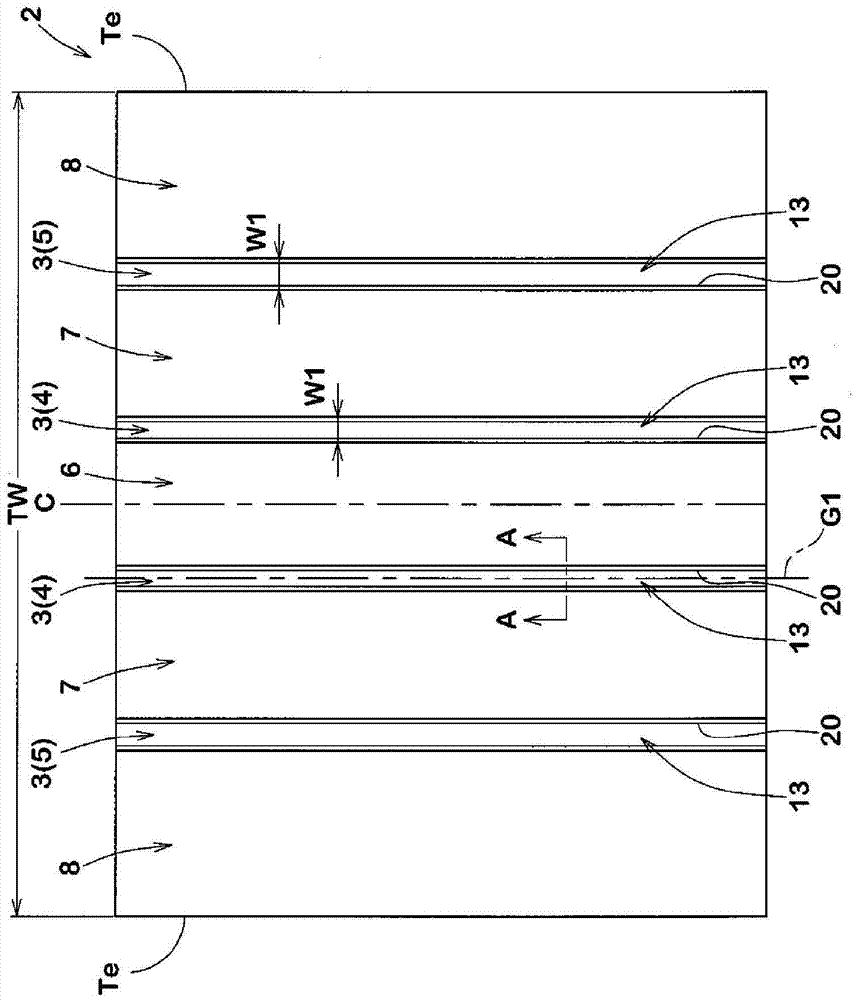
[0028] figure 1 is a developed view of the tread portion, showing an embodiment of the present invention. like figure 1 As shown in , the pneumatic tire (hereinafter, simply referred to as "tire") according to the present embodiment is suitable for use as, for example, a pneumatic tire for a passenger car. The tread portion 2 of the tire includes at least one main groove 3 extending continuously in the tire circumferential direction. The main groove 3 of the present embodiment includes a pair of central main grooves 4 extending on both sides of the tire equator line C and a pair of shoulder main grooves 5 . The shoulder main groove 5 extends axially outside the center main groove 4 .

[0029] The tread portion 2 of the present embodiment includes a central land portion 6 separated by a pair of central main grooves 4 , a pair of intermediate land port...


PUM


Abstract

Water discharge performance and noise performance are improved in a balanced manner. A pneumatic tire has a major groove (3) provided to a tread part (2). In a transverse cross section, the major groove (3) has a first groove wall (10), a second groove wall (11), and a groove floor (12). The groove floor (12) includes a protruding part (13) that is convex outward in a tire radial direction. The protruding part (13) continues along the major groove (3). The width (W3) of the protruding part (13) in a direction perpendicular to a groove center line (G1) of the major groove (3) is 50% to 100% of the groove width (W1) of the major groove (3). The protruding part (13) juts outward in the tire radial direction from an imaginary groove floor (12A) that connects an inner end (10i) of the first groove wall and an inner end (11i) of the second groove wall in a straight line, and the cross-sectional area of the protruding part (13) is 3% to 15% of the transverse cross-sectional area of the major groove (3).

Description

technical field [0001] The present invention relates to a pneumatic tire exhibiting drainage performance and noise performance in a balanced manner. Background technique [0002] In order to smoothly discharge the water film between the road surface and the tread surface of the tread portion toward the rear in the rotation direction of the tire, there is known a pneumatic tire including main grooves extending continuously in the circumferential direction of the tire. In order to improve the drainage performance of pneumatic tires, it is proposed to increase the groove volume of the main groove. [0003] However, when the groove volume of the main groove is increased, the rigidity of the groove bottom of the main groove tends to decrease. Therefore, when the tire touches the ground, the groove bottom of the main groove vibrates, and the groove bottom of the main groove vibrates the air flowing through the main groove, thereby generating air column resonance noise. Therefore...

Claims


Application Information

Patent Timeline
Patent Type & Authority Applications(China)
IPC IPC(8): B60C11/04B60C11/12B60C11/13
CPCB60C11/042B60C11/047B60C11/125B60C11/1353B60C2011/0353B60C2011/0355B60C2011/1361B60C11/0327B60C2011/0334B60C2011/0341
Inventor 岸田正宽
Owner SUMITOMO RUBBER IND LTD
Why Eureka
Try Eureka