
Method and device for extruding plasticized powdered materials (variants)

A powdery, extruded shaft technology, applied in the direction of ceramic extrusion dies, ceramic molding machines, manufacturing tools, etc., can solve the problem that people cannot obtain high-quality materials, do not provide the sufficient degree of the central area of ​​the billet, and cannot provide the degree and process and other issues to achieve the effect of enhancing homogeneity

Inactive Publication Date: 2016-03-30
OBSHCHESTVO S OGRANICHENNOY OTVETSTVENNOSTYU AVTOKLAVY VYSOKOGO DAVLENIYA I TEMPERATURY
View PDF5 Cites 3 Cited by
  • Summary
  • Abstract
  • Description
  • Claims
  • Application Information

AI Technical Summary

Problems solved by technology

For materials that require pressures as high as 10 to 50 MPa for molded articles, this method of processing compacted materials does not provide a sufficient degree of deformation treatment of the central area of ​​the billet, because for extruding these materials, the use of high Extruders to a bolt body diameter of 0.8 times the diameter of the press channel
In order to compact the material in the central area of ​​the billet, the use of such extruders requires a significantly high degree of material withdrawal which is technically not easily achievable, or the known solution does not provide such a degree and process of additional deformation thereof
For extruders with the same operating parameters, the use of known technical solutions does not allow one to obtain a high-quality material of the extruded powder (a rather high density gradient is observed in the section of the billet and a high residual porosity is observed in its central area )

Method used


Image

  • Method and device for extruding plasticized powdered materials (variants)
  • Method and device for extruding plasticized powdered materials (variants)
  • Method and device for extruding plasticized powdered materials (variants)

Examples


Embodiment Construction

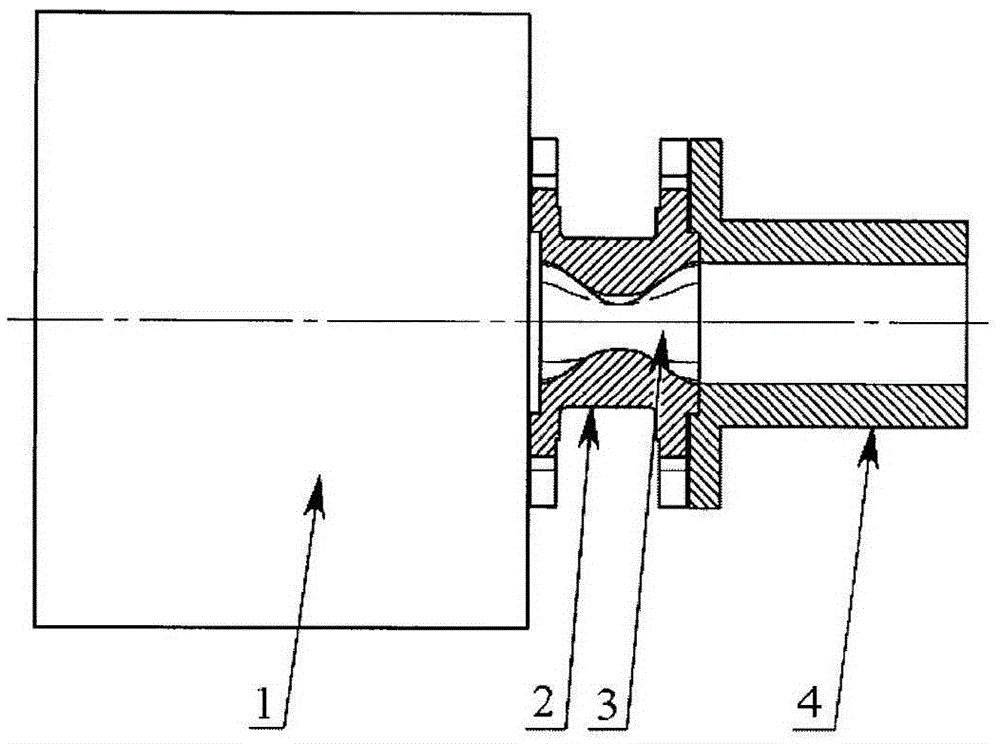
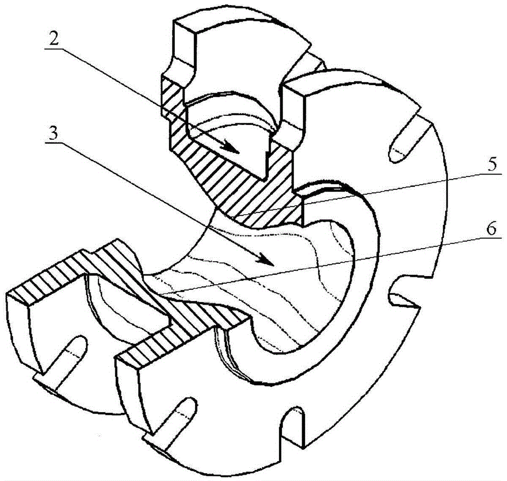
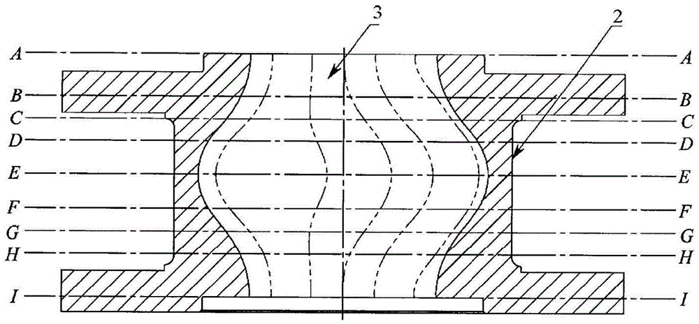
[0030] Devices for extruding plasticized powdered materials ( figure 1 ) comprising: an extruder 1, a deformation element 2 with a working (providing deformation) channel 3, and a forming die 4. In addition, the working channel 3 of the deformation element 2 has a ( figure 1 ) or multiple ( Figure 5 ) protruding part. The surface of each raised portion of the working channel 3 is constituted by two pairs of undulating surfaces 5, 6 in antiphase, symmetrical manner with respect to the axis of the working channel 3, and smoothly transitions from one to the other. In this case, for one pair of these surfaces, the greatest increase in the distance from the channel 3 surface to its axis lies in the plane 7 passing through said channel axis, while in the other pair such a greatest increase lies in On the raised surface, the generatrix 8 of said raised surface is perpendicular to the axis of the channel 3 along the entire length of the channel axis and also perpendicular to the p...


PUM

PropertyMeasurementUnit
porosityaaaaaaaaaa

Abstract

The invention relates to the field of producing long, pressed powder blanks by extrusion. The technical result of the invention is an increase in the density and uniformity of articles. A method for extruding plasticized powdered materials comprises forming a part blank from a material and forcing the part blank along an extrusion axis through a deformation channel having a variable cross-section. As the material is forced through the deformation channel, it is subjected to the simultaneous effect of oppositely signed cyclic drawing, shear and torsional strains as a result of the creation in the material of two oppositely signed cyclic compressive strains which are orthogonal to the extrusion axis and act in antiphase. The maximum increases in one of these compressive strains are set for the material in a plane which passes through the extrusion axis. The maximum increases in the second of these compressive strains are set for the material at the inlet and outlet of the deformation channel, orthogonal to the plane which passes through the extrusion axis. As the material is forced through the deformation channel, the directions of the maximum increases in the second compressive strain are changed by means of the rotation thereof about the axis of the channel according to any smooth periodic function having a period equal to the length of the deformation channel and an amplitude equal to 15-75 degrees.

Description

technical field [0001] The technical solution relates to the field of manufacturing long, compacted blanks from powders, in particular to methods and devices for extrusion of plastified and plastic powdered materials. Background technique [0002] Known methods for extruding plasticized powdered materials consist of extruding a starting billet and then forcing it through a deformation channel comprising one or more sections of variable cross-section, in each of which the material is forced along a vertical The direction of the pull-out direction undergoes two mutually perpendicular set deformations, and with respect to the previous set direction, the deformation direction at each subsequent part changes at an angle of 30-90° (RU patent 2272707C2, Int .Cl.B28B3 / 26, 2004). This method is mainly used for the manufacture of long articles from plasticized ceramic powders. [0003] Known devices for implementing the above-mentioned method include: an extruder, a deforming elemen...

Claims


Application Information

Patent Timeline
Patent Type & Authority Applications(China)
IPC IPC(8): B28B3/22B29C47/12B29C48/06B29C48/12B29C48/30
CPCB29K2509/02B28B3/26B29K2105/0038B29C48/022B29C48/267B29C48/03B29C48/12B29C48/06B29K2023/0683B29K2105/251B29C48/50
Inventor L·A·古边科V·E·佩雷尔曼
Owner OBSHCHESTVO S OGRANICHENNOY OTVETSTVENNOSTYU AVTOKLAVY VYSOKOGO DAVLENIYA I TEMPERATURY
Learn More