
Unmanned plane automation detection target and tracking method

An automatic detection and target tracking technology, which is applied in computer parts, character and pattern recognition, image data processing, etc., can solve the problems of easy tracking and loss, fixed surveillance cameras that cannot be deployed in all directions, etc.

Inactive Publication Date: 2016-03-30
SHANGHAI MARITIME UNIVERSITY
View PDF7 Cites 98 Cited by
  • Summary
  • Abstract
  • Description
  • Claims
  • Application Information

AI Technical Summary

Problems solved by technology

[0004] The technical problem to be solved by the present invention is to overcome the problem that the traditional fixed monitoring camera cannot be deployed in all directions, especially when the tracked object enters the monitoring blind area or the tracked object enters another camera area from one camera area, it is easy to track and lose. A method of automatic target detection and tracking using unmanned aerial vehicles

Method used


Image

  • Unmanned plane automation detection target and tracking method
  • Unmanned plane automation detection target and tracking method
  • Unmanned plane automation detection target and tracking method

Examples


Embodiment 1

[0093] This embodiment implements the whole process of parameter initialization of a UAV automatic detection target and tracking method.

[0094] 1. During the initialization process of the illumination compensation module, the input is a data set containing human faces and non-human faces. The processing process is: First, for the extracted color image X, set its red, green and blue components to be R, G, B. First, convert the original color image into a grayscale image. The conversion method is: For the R, G, and B components corresponding to each pixel X on the original color image, denote by i and j without loss of generality , Then the gray value of the gray image X′ corresponding to the pixel is X′(i,j)=0.3×B′(i,j)+0.59×G′(i,j)+0.11×R′( i, j), where X'(i, j) is an integer. If the result is a decimal, only the integer part is taken to obtain the original X grayscale image X'. Then, perform illumination compensation on the grayscale image, and send the result obtained after ...

Embodiment 2

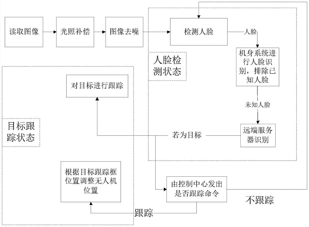
[0140] This embodiment realizes the whole detection process of an automatic detection target and tracking method of a UAV.

[0141] 1. The illumination compensation module, whose input is each frame of image taken by the drone, considering that the video image captured by the drone has a very small gap in its consecutive frames, and taking into account the drone's own processor The processing speed is limited, so it is not necessary to process each frame. You can select an appropriate frame interval for sampling according to the performance of the processor. The processing process is the same as that in Embodiment 1, and will not be repeated here. The result obtained after illumination compensation is sent to the image denoising module, and the illumination compensation process of the current frame by the illumination compensation module ends.

[0142] 2. Image denoising module, which passes the denoising processed picture to the face detection module. If the image needs to be deli...


PUM


Abstract

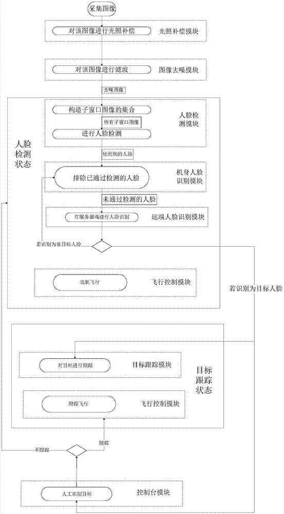
A unmanned plane automation detection target and tracking method is disclosed. An unmanned plane, a sonar distance detector installed on the unmanned plane, an illumination compensation module, an image de-noising module, a face detection module, a fuselage face identification module, a far-end face identification module, a target tracking module, a flight control module and a console module are included. The illumination compensation module carries out illumination compensation on an image. The image de-noising module carries out de-noising processing on the image. The face detection module carries out face detection on the received image. The fuselage face identification module identifies the detected face image and adds an identification result of the far-end face identification module. The far-end face identification module identifies the face image which can not be processed by a fuselage. The target tracking module tracks a target. The flight control module controls a movement track of the unmanned plane. The console module is manually monitored and emits various kinds of commands.

Description

Technical field [0001] The invention relates to the field of drone monitoring technology and computer vision, and specifically relates to a method for automatically identifying and tracking suspicious targets using drones. Background technique [0002] For target detection in the area, the traditional method is to use fixed surveillance cameras to detect targets (fugitives, important personnel, etc.) in the area. Since fixed monitoring needs to be fixed on the wall and connected to communication lines, the layout cost is high, and because People's increasingly high requirements for personal privacy make it impossible to arrange cameras in many residential areas, leaving a blind spot for monitoring. And because UAVs have good flexibility, so that the use of UAVs for automatic target detection and tracking has a very high flexibility. Existing drone monitoring usually transmits real-time images to the monitoring terminal. This method requires long signal transmission, takes up a l...

Claims


Application Information

Patent Timeline
IPC IPC(8): G06K9/00G06T7/20
CPCG06V40/161G06V40/172
Inventor 刘昱昊
Owner SHANGHAI MARITIME UNIVERSITY
Learn More