
Dryer

A dryer and drying tunnel technology, applied in dryers, drying, marine product drying, etc., to achieve the effects of convenient cleaning, stable air supply, and reduced drying time

Active Publication Date: 2016-03-30
WENZHOU XINGBEI MACHINERY TECH CO LTD
View PDF7 Cites 9 Cited by
  • Summary
  • Abstract
  • Description
  • Claims
  • Application Information

AI Technical Summary

Problems solved by technology

The inner walls of the dryer are insulated to prevent heat from escaping from the walls

Method used


Image

  • Dryer
  • Dryer
  • Dryer

Examples


Embodiment

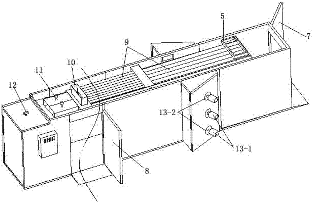
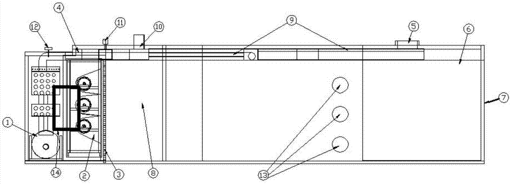
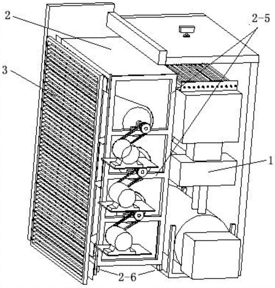
[0031] Embodiment: refer to attached Figure 1-9 , a kind of drying machine, comprises the shell of drying machine that inner wall is provided with insulation layer, air heating room, air supply room, drying tunnel, the air inlet 5 that communicates with air heating room, the air outlet 6 that communicates with the front end of drying tunnel, set The feed port 7 at the front end of the drying tunnel, the discharge port 8 at the rear end of the drying tunnel, a heat source heat exchanger 1 is provided in the air heating chamber, and a direct blowing air supply device 2 is provided in the air supply chamber. Type air supply device 2 comprises driving device 2-1, air channel plate 2-2, clapboard 2-3, centrifugal wind wheel 2-4, and one end of air channel plate 2-2 is arc-shaped, and the other end is an opening and External expansion; the centrifugal wind wheel 2-4 is set at the arc center of the air duct plate 2-2; the partition plate 2-3 is set on both sides of the end face of t...


PUM


Abstract

The invention relates to a dryer, which comprises a dryer housing, an air heating room, an air supply room, a drying channel, an air inlet which is communicated with the air heating room, an air outlet which is communicated with the front end of the drying channel, a material inlet which is formed in the front end of the drying channel, and a material outlet which is formed in the rear end of the drying channel, wherein a heat source heat exchanger is arranged in the air heating room; and a direct-blowing type air supply device is arranged in the air supply room. The dryer also comprises an air regulation guide plate, an exhaust waste heat recycling device, an intelligent fresh air humidity regulation device and a hot air compensation device. The dryer has the beneficial effects that the dryer can be used for drying laver and other products; constant-temperature and stable air supply can be realized; the air supply device is convenient to dismount, maintain and clean; the exhaust waste heat recycling function and partial exhaust recycling function are realized; thermal discharge is reduced and a product is energy-saving so that the production cost is reduced; and the hot air compensation device is capable of improving the drying efficiency of the dryer and shortening the drying time.

Description

technical field [0001] The invention relates to the field of seafood processing and the field of machinery, in particular to a dryer for drying laver products. Background technique [0002] Altar laver cannot be stored for a long time after harvesting, and needs to be dried. In the prior art, generally adopt the natural environment to dry or dry under the drying tunnel of civil construction. [0003] The coal-fired chimney pipe is installed on the parallel side of the drying tunnel; the axial flow fan is used to blow the wind to the coal-fired chimney pipe, and the hot air turns 180 degrees after the front end of the drying tunnel (the path of the wind is U-shaped steering). Entering the parallel drying tunnel, the whole is a civil structure, and the interior of the drying tunnel is an ordinary cart passage, without other designs. The hot air enters the rear end of the drying tunnel through the trolley, and is directly exhausted by the exhaust fan at the rear end. The sim...

Claims


Application Information

Patent Timeline
Patent Type & Authority Applications(China)
IPC IPC(8): F26B21/00A23L17/60A23N12/08
CPCA23N12/08F26B21/004F26B2200/16Y02P60/85
Inventor 张明水潘峰
Owner WENZHOU XINGBEI MACHINERY TECH CO LTD
Learn More