


Quick Research
Generate reliable direction feasibility study reports for your R&D in just a few steps.

Technical Q&A
Discover and master advanced knowledge NOW. Basics, ideas, possibilities, all at once.

Find Solutions
As an expert in R&D theories, this can generate solutions to your technical problems instantly.

Evaluate Feasibility
Analyze your overall solution with one click, know your potential R&D risks in advance.

Monitor Landscape
Get weekly tech updates, stay abreast of the latest tech innovations and key insights.
A household gas valve
A valve and gas technology, applied in the direction of valve details, safety valves, balance valves, etc., can solve problems such as user safety not being guaranteed, high indoor temperature, and gas pipeline safety, so as to ensure personal safety and property safety, and improve The effect of safety performance
- Summary
- Abstract
- Description
- Claims
- Application Information
AI Technical Summary
Problems solved by technology
Method used
Image

Examples
Embodiment 1
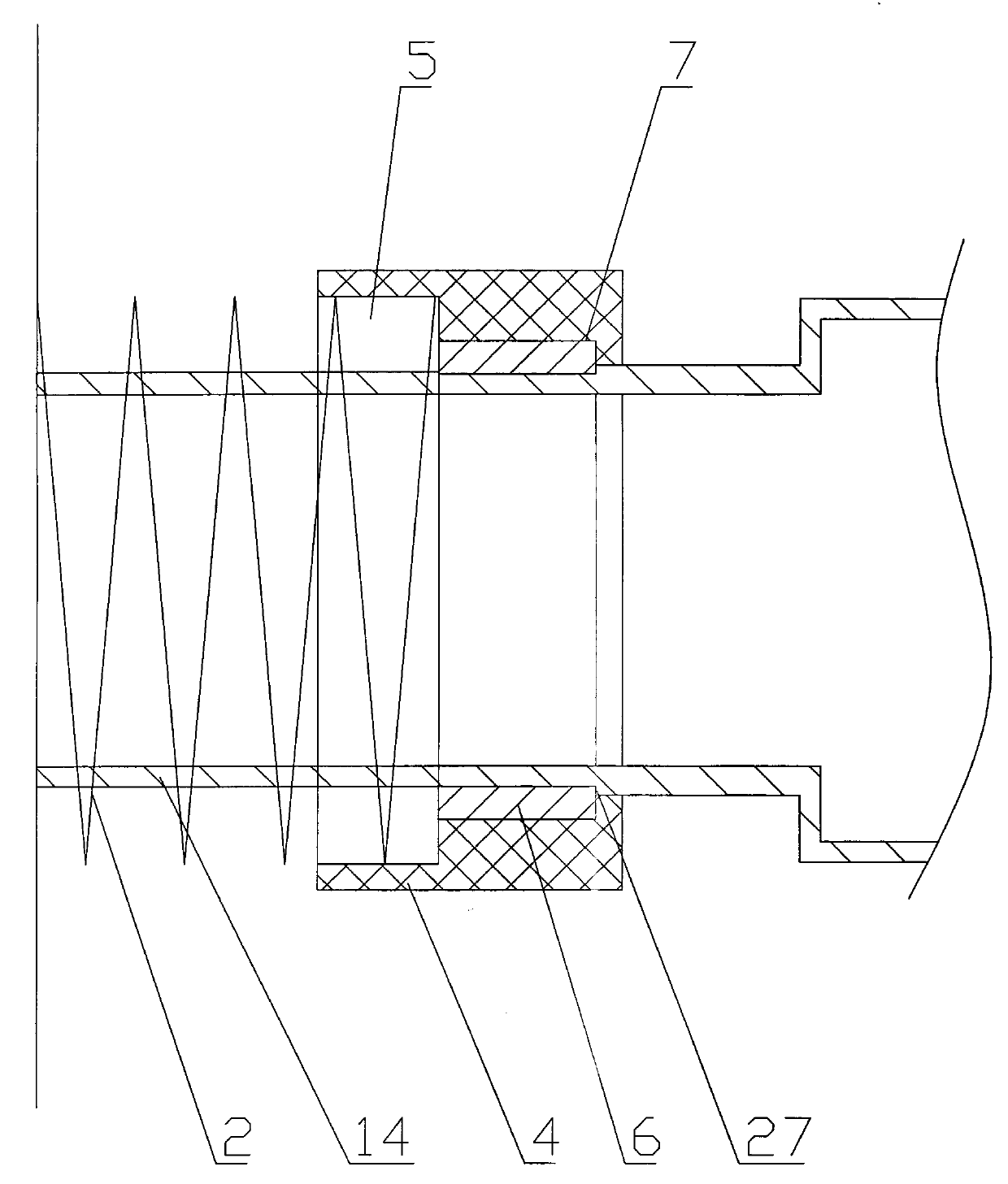
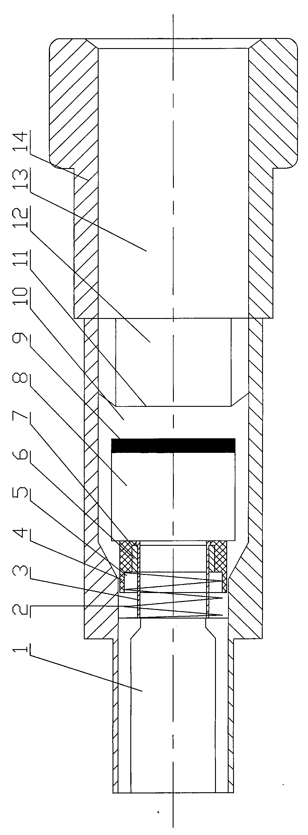
[0019] Embodiment one, with reference to figure 1 , a domestic gas valve, including a valve body 14, the valve body 14 has a gas passage 13, the gas passage is divided into an air intake section 1, a switch section 10 and an air outlet section 12, the gas passage switch section 10 The inner diameter is larger than the inner diameter of the inlet end 11 of the gas outlet section, and a sliding block 8 for sealing is arranged in the gas channel 13. The bottom surface area of the slider 8 is smaller than the cross-sectional area of the gas channel switch section 10, and is larger than the inlet end of the gas channel outlet section. 11, the bottom surface of the slider 8 is provided with a gasket 9, and the valve also includes a thermal sensor that pushes the slider 8 to move, and the thermal sensor is arranged in the valve body 14, and the thermal sensor The sensitive sensor includes an induction sleeve 4, a fixed block 6 and a spring 2. The induction sleeve 4 has an annular...
Embodiment 2
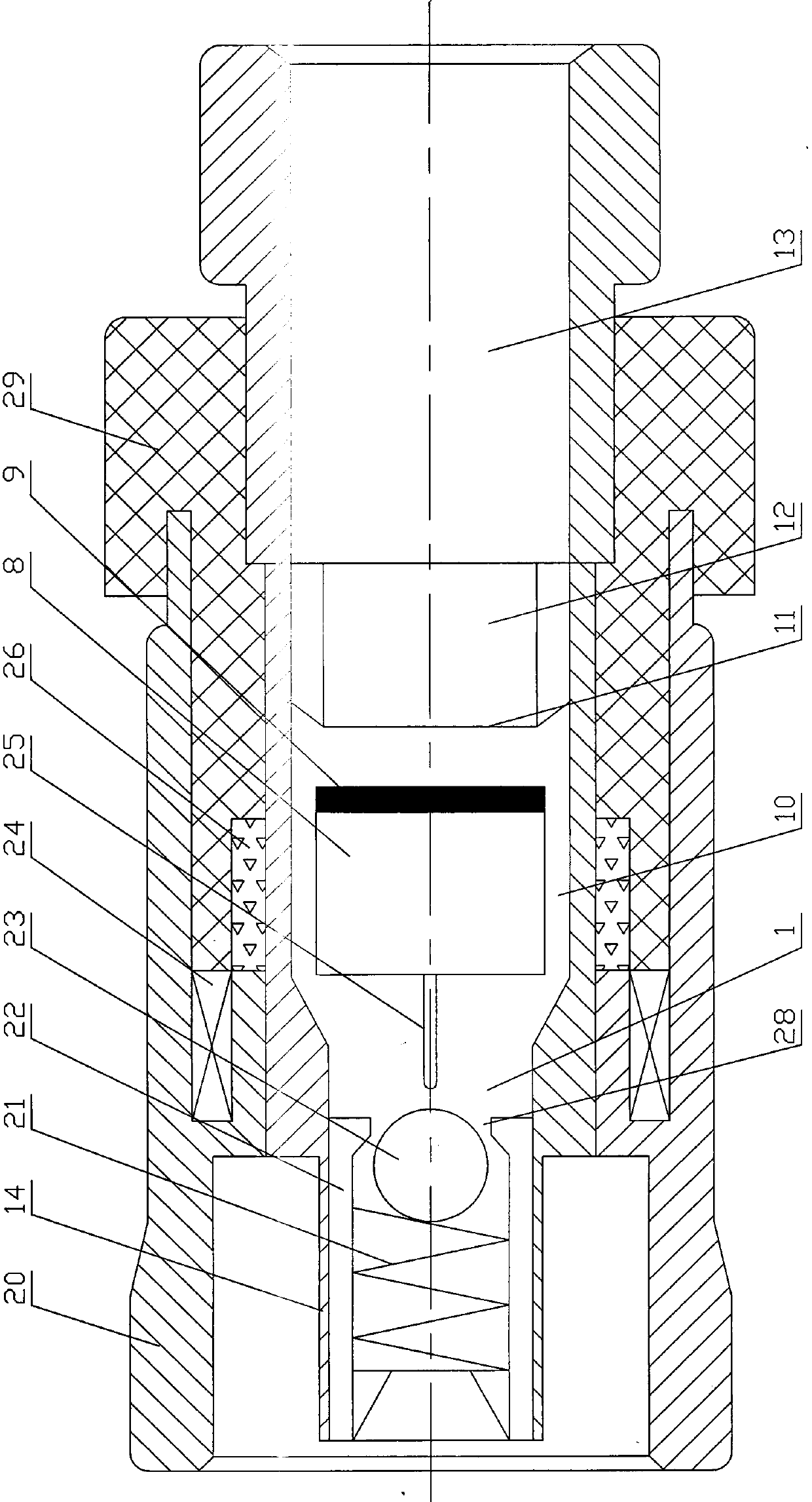
[0020] Embodiment two, referring to the attached figure 2 , this kind of domestic gas valve includes a valve body 14, a casing 20 and a manual button, the manual button 29 is set outside the valve body 14, the casing 20 is set outside the manual button 29, the valve body 14 One end is inserted into the casing 20 and is threadedly connected with the inner wall of the casing 20. The valve body 14 has a gas channel 13. The manual button 29 can move axially relative to the casing 20 and the valve body 14. The manual button 29 is provided with a magnetic ring 26; the gas channel 13 is divided into an air intake section 1, a switch section 10 and an air outlet section 12, the inner diameter of the gas channel switch section 10 is greater than the inner diameter of the inlet port 11 of the air outlet section, and a sealing Use the slider 8, the slider 8 and the magnetic ring 26 induction, the slider 8 can be iron, the bottom surface area of the slider 8 is smaller than the cross-s...
PUM
 Abstract
Description
Claims
Application Information
 - R&D Engineer
- R&D Manager
- IP Professional
- Industry Leading Data Capabilities
- Powerful AI technology
- Patent DNA Extraction
Browse by: Latest US Patents, China's latest patents, Technical Efficacy Thesaurus, Application Domain, Technology Topic, Popular Technical Reports.
© 2024 PatSnap. All rights reserved.Legal|Privacy policy|Modern Slavery Act Transparency Statement|Sitemap|About US| Contact US: help@patsnap.com